Automatic gauge control (AGC) keeps steel strip and plate at the target thickness by adjusting the roll gap many times per second. When AGC works well, more of every coil sits inside tolerance, head ends are shorter and customers stop sending claims. When it drifts, the cause is usually mechanical. Common culprits are a dirty servo valve, a leaking cylinder, a drifting load cell or an X-ray gauge out of calibration.
That makes AGC optimization a joint job for process engineers and the maintenance team. This guide explains how the control loops work, why performance degrades and how to restore it with the GAUGE Framework. You also get a troubleshooting matrix and a maintenance schedule. Finally, it shows how a Computerized Maintenance Management System keeps the gains in place.
Key Takeaways
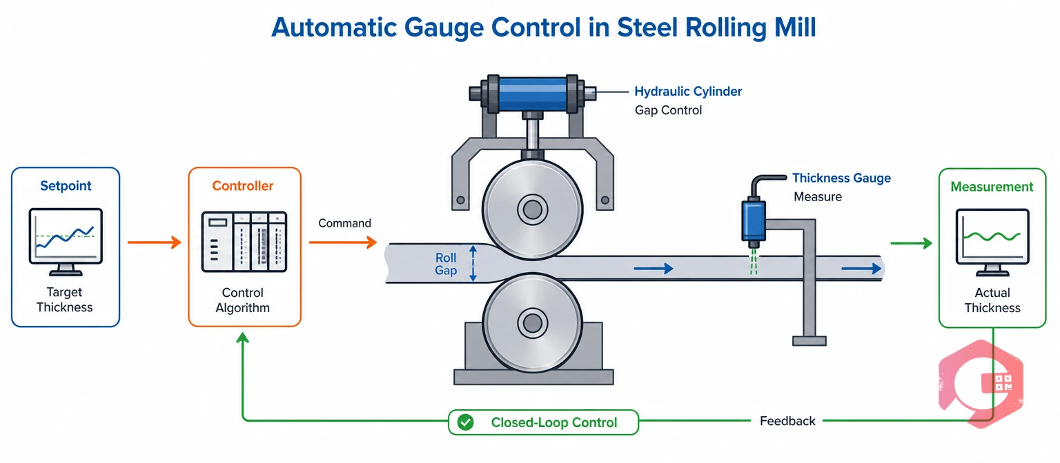
Automatic gauge control (AGC) is a closed-loop system that adjusts the roll gap of a rolling mill to keep strip thickness on target. It runs on hot strip mills, plate mills, Steckel mills and cold rolling mills, and it reacts faster than any operator could.
Thickness varies because the material entering the stand is never uniform. Temperature changes, hardness changes and incoming gauge changes all alter the rolling force. As force changes, the mill stand stretches like a spring, and the gap opens or closes. AGC measures that effect and moves the rolls to cancel it.
Reliability standards apply here too. ISO 55000 asks owners to manage assets for value over their whole life. RCM and FMEA studies should list AGC parts as critical to quality. A mill that treats AGC hardware as ordinary auxiliary equipment usually pays for it in off-gauge coils.
Automatic gauge control works as a stack of loops. A fast inner loop holds the cylinder position, and slower outer loops decide where that position should be.
Hydraulic gap control (HGC) is the fast position loop that moves the hydraulic cylinders to set the roll gap. It compares the position reference with the transducer reading and drives the servo valve to close the error. Every outer AGC mode depends on this loop being fast, stable and free of friction.
Thin strip leaves little room for error. On a 1 mm strip, a 10 micron error is already 1% of the gauge. The HGC loop must react in a few milliseconds to catch it. A slow or sticky loop lets each disturbance print onto the strip before it is corrected.
Mill modulus is the force needed to stretch the mill stand by one millimetre, usually given in kN per mm. The gaugemeter (BISRA) method estimates exit thickness as the unloaded roll gap plus rolling force divided by mill modulus.
Here is a simple example. With a mill modulus of 5,000 kN/mm, a force rise of 500 kN stretches the stand by 0.1 mm. If AGC did nothing, the strip would come out 0.1 mm thicker.
Each loop needs accurate inputs. A drifting load cell corrupts the gaugemeter estimate, and a dirty speed sensor corrupts mass flow. Good automatic gauge control is only as good as its weakest sensor.
Each automatic gauge control mode corrects a different source of thickness error. Most modern mills combine several modes. Knowing what each one needs helps you focus maintenance where it counts.
| Control Mode | Main Input | What It Corrects | Main Limitation | Hardware It Depends On |
|---|---|---|---|---|
| Gaugemeter (BISRA) AGC | Roll force and gap position | Fast changes in hardness and temperature | Relies on an accurate mill modulus and zero point | Load cells, position transducers, HGC cylinders |
| Monitor (feedback) AGC | Exit thickness gauge | Slow drift and model error | Transport delay between stand and gauge | Exit X-ray gauge, strip speed signal |
| Feedforward AGC | Entry thickness gauge | Incoming gauge variation before it reaches the stand | Needs exact tracking of strip position | Entry gauge, speed sensors, fast HGC |
| Mass flow AGC | Entry and exit strip speeds | Thickness changes on cold mills with high accuracy | Sensitive to speed measurement error | Laser velocimeters or bridle roll encoders |
| Eccentricity compensation | Force or gap signal per roll revolution | Cyclic errors from roll and bearing eccentricity | Must be retuned after roll changes | Roll position encoders, load cells |
The pattern is clear: every mode leans on a different sensor or actuator. If thickness performance drops, the control mode that weakens first tells you which hardware to check.
Thickness errors cost output as well as quality. Use the free OEE calculator to see how off-gauge scrap and AGC-related stops pull down your mill's overall performance.

AGC performance drops when the parts that measure and move the roll gap wear or drift. Most maintenance teams in steel plants see the same six causes again and again.
Servo valves have tight clearances, and dirt particles wear the spool and sleeve. Valve makers commonly ask for hydraulic oil cleanliness around ISO 4406 16/14/11 or better, so check your OEM limit. A worn valve shows up as null drift, slow response and higher leakage.
Worn or hardened seals add friction, which causes stick-slip motion at small corrections. Internal leakage makes the position loop work harder and can let the gap creep under load. Both reduce the fine control that thin gauges need.
A position sensor that drifts by a few microns shifts every thickness estimate. Load cells drift with heat, moisture and overload, which corrupts the gaugemeter calculation. Regular calibration is the only defense.
X-ray gauges need routine checks with reference samples. Cooling, alignment and clean windows matter too. Isotope gauges also face source decay and strict radiation safety rules. An uncalibrated gauge pushes monitor AGC to the wrong target.
Out-of-round backup rolls and worn oil film bearings create a cyclic force signal. AGC can mistake it for a thickness change and react in the wrong direction. Grinding quality and bearing condition directly affect thickness variation.
Accumulators supply oil during fast gap moves. If their gas charge is low, pressure dips just when AGC needs it most. Hot oil causes trouble too. It thins out, leaks more past seals and ages faster. Keep oil temperature in the OEM range and check pre-charge each month.
Worn liners let chocks shift inside the mill housing. That changes the mill modulus and adds hysteresis that no control tuning can remove. Measuring window clearances at planned outages keeps this in check.
Each of these is a maintenance item, not a software bug. Fix the hardware first and the controls will often recover most of their lost performance.
Use this matrix when thickness performance drops or an AGC alarm repeats. Match the symptom first, then check the likely component before you change any controller settings.
| Symptom | Likely Cause | Component to Check | First Check |
|---|---|---|---|
| Thickness swings once per backup roll revolution | Roll eccentricity | Backup rolls, bearings | Eccentricity compensation status and last grind record |
| Slow, steady offset from target | Gauge or zero-point error | Exit X-ray gauge, gap zero | Gauge standardization and last zero-point calibration |
| Long off-gauge head ends | Weak feedforward or slow HGC | Entry gauge, servo valve | HGC step response and strip tracking accuracy |
| Gap creeps under steady load | Internal cylinder leakage | HGC cylinder seals | Leak test with valve closed and gap held |
| Small corrections overshoot or hunt | Seal friction or valve wear | Cylinder seals, servo valve | Valve null current and small-step response test |
| Thickness error grows during the shift | Thermal drift | Load cells, transducers, oil temperature | Oil temperature trend and sensor drift |
| Repeated servo valve faults | Contaminated hydraulic oil | Filters, oil system | Particle count and filter differential pressure |
| Thickness differs from operator side to drive side | Uneven stretch or sensor mismatch | Both HGC cylinders, load cells | Side-to-side calibration and liner clearance |
Log every match as a work order with the symptom, cause and fix. Over time, that history shows which components fail most and where your PM plan needs to change.
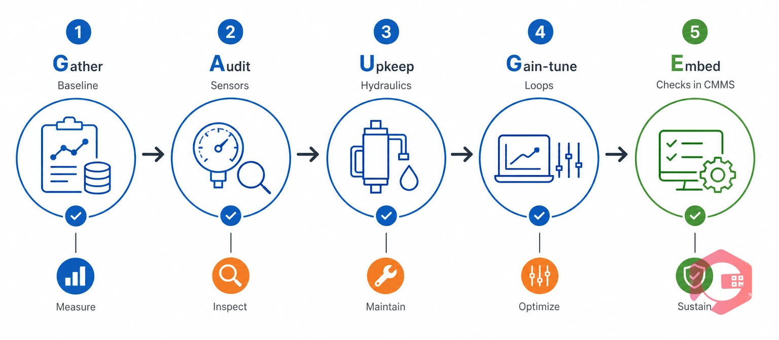
The GAUGE Framework is a shared plan for automatic gauge control optimization. Maintenance and process teams follow the same steps. It starts with data and ends with routine checks, so improvements do not fade after the project team moves on.
The GAUGE Reliability Framework:
Tuning before repair is a common mistake. If a servo valve is worn, new gains simply hide the problem until the valve fails outright. Audit and repair first, then tune, so the controller works with equipment in known condition.
Operations that run GAUGE as a loop, not a one-off project, usually keep thickness performance stable between major outages. The framework turns automatic gauge control optimization into a repeatable routine.
An AGC maintenance schedule links each critical component to a task, an interval and a trigger. Use this schedule as a starting point, then adjust it to your OEM manuals, mill type and failure history.
| Component | Maintenance Task | Typical Frequency | Failure Prevented | CMMS Trigger |
|---|---|---|---|---|
| Hydraulic oil system | Particle count, water content and filter differential pressure | Weekly to monthly | Servo valve wear and sticking | Calendar plus oil sensor alarm |
| Servo valves | Null and response check; replace or overhaul on condition | Quarterly or on condition | Slow response and gap drift | Condition-based |
| HGC cylinders | Leak test and seal inspection | At planned outages | Gap creep and stick-slip | Outage work package |
| Position transducers | Calibration against reference positions | Monthly or at roll change | False gap readings | Meter-based (roll changes) |
| Load cells | Calibration and cable inspection | Quarterly | Wrong force and stretch estimates | Calendar |
| X-ray or isotope gauge | Standardization with reference samples; check cooling and windows | Per shift to weekly | Wrong thickness target | Calendar plus shift checklist |
| Accumulators | Check nitrogen pre-charge | Monthly | Pressure dips during fast moves | Calendar |
| Backup roll bearings and chocks | Inspect bearings, liners and window clearances | At roll change and outages | Eccentricity and modulus change | Meter-based (tonnage rolled) |
Load these tasks into preventive maintenance software. Each one then creates a work order on time, with the right checklist attached. A schedule only protects automatic gauge control when the work is done and recorded.
The right KPIs show if AGC optimization is working. They also show if equipment condition is holding. Track quality and reliability measures side by side, because a fall in one often predicts a fall in the other.
Thickness performance also feeds overall equipment effectiveness through the quality factor. Better automatic gauge control raises OEE without adding a single extra hour of rolling time.
A CMMS keeps automatic gauge control reliable. It turns calibration, inspection and repair into tracked work with a full history. Without it, AGC knowledge lives in a few engineers' notebooks.
Calendar schedules suit some tasks, but many AGC checks depend on usage. Meter-based PMs fix that. They can trigger sensor calibration after a set number of roll changes. They can also trigger chock checks after a set tonnage.
Condition monitoring software can pull hydraulic data from PLCs or SCADA. That includes oil temperature, particle counts, filter pressure and valve current. When a value crosses its limit, the system raises a work order before thickness quality suffers.
With downtime tracking, every AGC-related stop is recorded against the stand and component. Repeat faults then stand out, and teams can run a 5 Whys review on the real cause.
Autonomous maintenance fits AGC well. Operators can log gauge checks, oil leaks and alarm counts each shift on a mobile checklist. Small problems then reach maintenance early.
Maintenance teams using Cryotos have reported up to 30% reduction in unplanned downtime and 25% faster repair turnaround. For AGC, the added gain is proof: thickness KPIs and maintenance records sit side by side, so you can show which repairs improved quality. Cryotos also supports steel and metals plants through its manufacturing maintenance software.
Automatic gauge control keeps strip or plate thickness on target by adjusting the roll gap in real time. It uses roll force, gap position, strip speed and thickness gauge readings to correct for changes in temperature, hardness and incoming thickness.
AGC performance usually drops because the equipment behind it wears or drifts. The most common causes are dirty hydraulic oil, worn servo valves and leaking cylinder seals. Drifting sensors and uncalibrated gauges come close behind.
It depends on the component and your OEM guidance. X-ray gauges are often standardized every shift or day, position transducers at roll changes, and load cells every few months. Record each result so you can spot drift trends.
Repair first. Tuning gains on worn hardware hides the fault and makes the system less stable when the part finally fails. Once valves, seals and sensors are in good condition, retune the loops on a clean baseline.
The gaugemeter equation estimates exit thickness as the unloaded roll gap plus rolling force divided by the mill modulus. It lets AGC react to force changes immediately, without waiting for a downstream gauge reading.
A CMMS schedules calibrations and hydraulic checks, records the results and links AGC faults to downtime and root causes. It turns AGC upkeep into routine work, so thickness performance holds between major outages.
Consistent thickness starts with consistent equipment care. Schedule a free demo to see how Cryotos plans AGC calibrations, tracks hydraulic health and links each thickness problem to its fix.



Cryotos AI predicts failures, automates work orders, and simplifies maintenance—before problems slow you down.