Your compressor just crossed 85°C for the third time this week. Did your CMMS automatically create a work order? If not, you're running on a time-based schedule that doesn't know your equipment's actual condition — and that gap costs you unplanned downtime, wasted labour, and parts replaced too early or too late. Condition-based PM triggers change that. Instead of relying on the calendar, your IoT sensors watch the equipment in real time and fire a maintenance task the moment a reading crosses a threshold that actually matters. This guide walks you through every step: choosing sensors, defining thresholds, wiring data into your CMMS, and configuring the trigger logic so the right work order lands in the right technician's queue without anyone pressing a button.
Key Takeaways
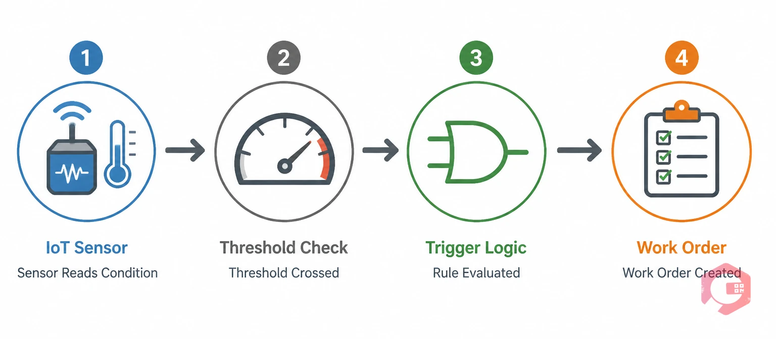
A condition-based PM trigger is a rule inside your CMMS that monitors one or more sensor readings and automatically creates a preventive maintenance work order when a reading exceeds a defined condition. Unlike a time-based PM that fires every 30 days whether the machine needs attention or not, a condition-based trigger only acts when the data says something is changing.
The logic is simple: if vibration on Pump A crosses 12 mm/s RMS for more than 10 minutes, create a bearing inspection work order, assign it to the rotating equipment team, attach the lubrication checklist, and set priority to High. Your IoT meter reading module captures the sensor value, compares it against your rule, and hands the instruction to your work order management engine — all in seconds, with no human in the loop.
Understanding the difference helps you decide which assets to move to condition-based triggers first.
| Dimension | Calendar-Based PM | Condition-Based PM Trigger |
|---|---|---|
| Trigger source | Fixed date/time interval | Live sensor reading |
| Maintenance timing | Fixed (every 30 days, 500 hours) | Dynamic — only when needed |
| Risk of over-maintenance | High — parts replaced too early | Low — work triggered by actual wear |
| Risk of under-maintenance | High — fast-degrading assets missed | Low — threshold catches early signs |
| Setup complexity | Low — set a frequency and done | Medium — requires sensors + rules |
| Best for | Low-criticality, uniform-use assets | High-criticality, variable-use assets |
Every condition-based PM trigger has four links in the chain. The sensor collects the physical measurement (vibration in mm/s, temperature in °C, pressure in bar). The threshold defines what "abnormal" looks like for that asset and operating context. The logic layer applies rules — single or combined — to decide whether the condition is confirmed. The CMMS then acts: creating the work order, setting the type, assigning the team, and attaching the right checklist.
Break any link in that chain and the trigger either misses real faults or creates noise. The five steps below walk you through building each link correctly.
Not every asset needs every sensor type. Matching the sensor to the failure mode you're trying to catch is the most important decision you'll make — get it right and your triggers are precise; get it wrong and you're measuring the wrong thing and wondering why your alerts keep missing faults.
Accelerometers and velocity sensors mounted on bearing housings, motor end-bells, and pump casings detect imbalance, misalignment, looseness, and bearing defects. According to the ISO 10816 machinery vibration standard, velocity readings above 7.1 mm/s RMS indicate incipient damage on most industrial machines. These are your highest-ROI sensors for rotating equipment because early vibration changes appear weeks or months before catastrophic bearing failure.
RTDs, thermocouples, and non-contact infrared sensors flag overheating in motor windings, electrical panels, gearboxes, and hydraulic fluid. A temperature rise of even 10°C above baseline in a motor bearing is a strong indicator of lubrication breakdown or overload. Temperature sensors are cheap, easy to retrofit, and integrate cleanly with most IoT gateways.
Pressure drop across a filter, abnormal line pressure, or pressure fluctuation in a hydraulic circuit each signal specific failure modes: clogged filters, worn seals, or pump cavitation. Pressure sensors work well as secondary confirmations alongside vibration — for example, high vibration AND low pressure on a hydraulic pump strongly points to cavitation, which requires a different response than vibration alone.
Clamp-on current transformers (CTs) non-invasively monitor motor current. An increase in current draw on a pump often indicates rising mechanical resistance from wear, debris, or cavitation — before the vibration signature becomes obvious. Power draw monitoring is particularly useful when physical sensor mounting is difficult or impractical.
In-line oil sensors measure particle count, viscosity, water contamination, and oxidation. They're the go-to for high-value assets like large gearboxes, turbines, and heavy vehicle engines where oil analysis traditionally required lab sampling and a multi-day turnaround. Inline sensors close that loop to minutes, turning an infrequent lab test into a continuous condition trigger.
Thresholds are where most condition-based PM programs fail. Set them too tight and you flood the CMMS with false alarms; set them too loose and real faults slip through. There are three concepts every maintenance engineer needs to understand before writing a single rule.
A hard limit is a single value that, once crossed, triggers an immediate high-priority work order — or even an automated shutdown. Think motor winding temperature above 155°C or gearbox vibration above 25 mm/s. A soft warning band sits below the hard limit and creates a lower-priority inspection task: "bearing temperature has been between 85°C and 100°C for 4 hours — schedule a lubrication check within 48 hours." Running both layers in your CMMS means you catch developing issues early while still flagging emergencies urgently.
Without hysteresis, a sensor fluctuating around a threshold creates a storm of repeated triggers — alarm on, reading drops slightly, alarm off, reading rises, alarm on again. Hysteresis prevents this by requiring the value to drop a defined amount below the trigger threshold before the alarm resets. For example: trigger ON at 90°C, reset OFF only when the reading drops to 82°C. Your CMMS only creates one work order for the event, not dozens. The ISA alarm management guidelines recommend hysteresis bands of 5–15% of the trigger value for most process sensors.
A debounce window requires a threshold to remain exceeded for a minimum duration before the trigger fires. A single spike to 91°C for 0.3 seconds is noise; a sustained reading above 90°C for 10 minutes is a real thermal event. Debounce windows are especially critical for vibration sensors near equipment that creates transient mechanical shocks (presses, hammers, drop-forges) where single-reading spikes are common and expected.
Getting sensor data into your preventive maintenance software requires a data path from the physical sensor to the CMMS rule engine. There are three main architectures, and the right choice depends on your site's existing infrastructure.
If your plant already runs SCADA (Supervisory Control and Data Acquisition) or PLC (Programmable Logic Controller) networks, the cleanest approach is to push sensor tags from those systems into your CMMS via an OPC-UA or MQTT data bridge. The SCADA system continues to own process control; the CMMS subscribes to the maintenance-relevant tags and applies PM trigger rules on top. This architecture keeps control and maintenance logic separate, which is critical for safety-certified environments.
Edge gateways (industrial IoT hubs like those from Moxa, Advantech, or Siemens) sit between your sensors and the cloud. They process raw sensor streams locally — applying filtering, feature extraction, and threshold logic — and send only event notifications to the CMMS. This reduces latency from minutes to milliseconds, cuts cloud data transfer costs, and keeps your PM triggers working even during network outages. According to NIST guidance on IIoT architectures, edge processing is the recommended pattern for latency-sensitive condition monitoring applications.
Cloud-native IoT platforms (AWS IoT, Azure IoT Hub, Google Cloud IoT) can push sensor readings directly to your CMMS via REST or webhook integrations. This is the simplest path for new installations with no existing SCADA infrastructure. Your sensors connect to the cloud platform, which applies basic filtering, and the CMMS API receives trigger events. It's less resilient during internet outages but easier to configure and scale.
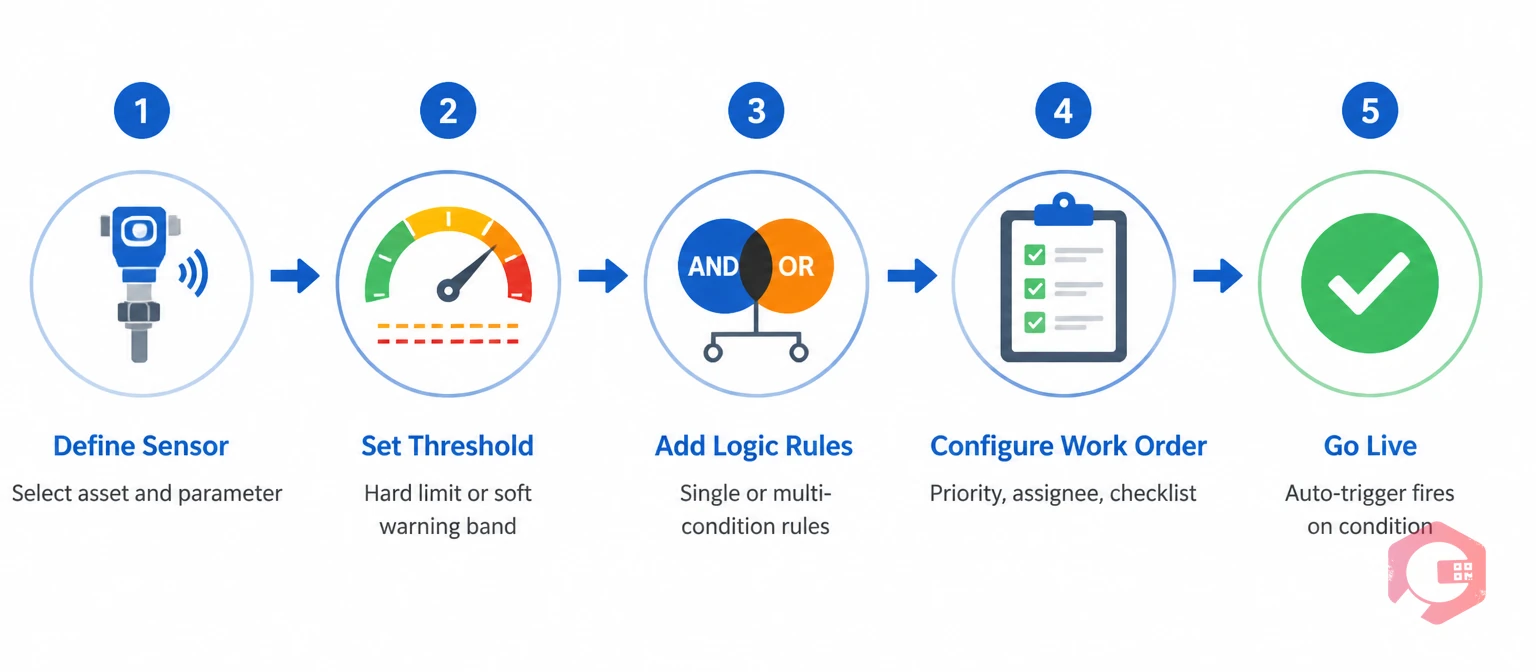
With sensors connected and thresholds defined, you now build the rules that turn data into action. Most modern CMMS platforms — including Cryotos — let you define condition triggers through a rule builder that maps sensor readings to work order templates. Here's how to approach the logic layer.
The simplest trigger: one sensor, one threshold, one work order. "If bearing temperature on Air Compressor 3 exceeds 95°C for 15 minutes, create a 'Bearing Thermal Inspection' work order, assign to the electrical team, priority Medium." Start here for all new assets. Single-condition triggers are easy to validate (you can force-test them by heating a sensor with a heat gun or injecting a test value) and easy to tune without complex interdependencies.
Once your single-condition triggers are running cleanly, layer in multi-condition rules to catch complex failure modes. AND logic confirms a fault from multiple angles before acting: "bearing temperature above 90°C AND vibration above 8 mm/s AND current draw up 15% from baseline → create urgent bearing replacement work order." This dramatically reduces false positives. OR logic catches faults that may show up in different sensors depending on the failure path: "bearing temperature above 95°C OR vibration above 12 mm/s → create bearing inspection work order." Both patterns are standard in industrial condition monitoring practice.
An auto-triggered work order is only useful if the right person gets it with the right instructions. Configure your CMMS trigger to pre-populate: the work order type (inspection, lubrication, replacement), priority level (Low/Medium/High/Critical based on threshold severity), the default assignee or team, the asset and location fields, and the maintenance checklist. Cryotos lets you attach dynamic workflow automation templates to triggers so technicians receive step-by-step instructions the moment the task hits their queue — no manual setup required per event. Use the IoT sensor deployment validation checklist to verify your setup before going live.
A condition-based PM trigger you haven't tested is a liability. Before relying on automated triggers for critical assets, put every rule through a validation cycle.
Most CMMS platforms support a simulation or test mode where you inject a fake sensor reading to verify the trigger fires correctly. Walk through each rule: inject a reading above the threshold, confirm the work order is created with the right type, priority, assignee, and checklist. Then inject a reading below the threshold and confirm no work order is created. Log the results — this becomes your baseline documentation for the trigger configuration audit.
After two weeks of live running, pull your triggered work order log and categorise each one: genuine fault found, genuine fault not found, nuisance alarm. If false positives exceed 20% of triggered tasks, your threshold is too tight, your debounce window is too short, or your sensor is in a noisy location. A 5–10% false positive rate is typical for well-tuned systems and is acceptable because the cost of a missed genuine fault far exceeds the cost of an extra inspection.
Initial thresholds are educated guesses until you have real operating data behind them. After 30 days, review your condition-based maintenance trigger logs and ask: which thresholds fired most often, which caught real faults, which generated noise? Adjust in small increments — raise a threshold by 5–10% if false positives are high, lower it if real faults were caught only after the reading had been elevated for days. After 60 days you should have thresholds that reflect the actual operating envelope of each asset.

Even experienced maintenance engineers make these mistakes when implementing condition-based triggers for the first time.
Vibration sensors (accelerometers/velocity sensors), temperature sensors (RTDs, thermocouples, infrared), pressure sensors, current/power draw sensors, and oil quality sensors are the five most commonly integrated sensor types. The best type for a given asset depends on its dominant failure modes — start with vibration for rotating equipment and temperature for electrical and thermal assets.
This depends on your debounce window configuration. A single reading above a hard threshold is enough for an emergency trigger on critical assets. For standard PM triggers, requiring the threshold to be exceeded for a minimum duration — typically 5 to 30 minutes depending on the failure speed of the equipment — prevents noise-driven false positives while still catching real developing faults well before failure.
Yes. Wireless MEMS accelerometers and temperature sensors now cost under $200 per point, and many cloud IoT platforms offer free tiers for small sensor counts. The real investment is in threshold engineering and CMMS configuration, not hardware. For assets where wired sensors aren't practical, ultrasound guns and handheld thermography cameras can feed manual readings into a CMMS threshold rule as a lower-cost starting point.
Properly configured hysteresis, debounce windows, and multi-condition AND/OR logic together prevent most false alarms. Hysteresis stops alarm chatter at threshold boundaries. Debounce windows filter transient spikes from process noise. AND logic requires confirmation from multiple sensors before firing a trigger. Most teams reach a false positive rate of 5–10% after 60 days of tuning — far lower than time-based systems where every scheduled PM is a "potential false positive" if the machine is actually fine.
When you're ready to connect your sensor data to a maintenance workflow that actually triggers the right work order at the right time, Cryotos CMMS is built for exactly this. The IoT meter reading module pulls in live sensor feeds, the rule builder lets you configure single and multi-condition triggers with AND/OR logic, and every triggered event lands directly in your preventive maintenance software queue with the right team, checklist, and priority already set. Schedule a Demo to see how Cryotos handles condition-based PM triggers from your specific sensor types.


Cryotos AI predicts failures, automates work orders, and simplifies maintenance—before problems slow you down.