
Hardware-in-Loop (HIL) testing is a real-time simulation method that connects physical hardware components — controllers, sensors, actuators — to a virtual model of the system they will operate in, allowing engineers to validate and stress-test equipment under realistic conditions without deploying it in the field. In predictive maintenance (PdM) pipelines, HIL sits at a critical junction: it generates the labeled failure-mode data that machine learning models need to become accurate, and validates the sensor thresholds and alert logic before they go live on production assets. According to a NASA technical report on reliability engineering, organizations that validate sensor-trigger logic through hardware-level testing before deploying predictive models reduce false-positive maintenance alerts by up to 60%.
Key things HIL testing does for a PdM pipeline

Hardware-In-Loop testing is a closed-loop testing methodology where a physical device under test (DUT) — typically a controller, ECU, or sensor node — interfaces with a real-time simulation platform that mimics the behavior of the rest of the system. The hardware thinks it is operating in a real environment. The simulation responds to its outputs and feeds back realistic inputs, creating a continuous loop that exposes the hardware to the full range of operating conditions without touching the actual plant or machine.
The three core components of a HIL test setup are:
Unlike pure software simulation (Software-in-Loop or Model-in-Loop), HIL testing involves real hardware responding to real electrical signals. This matters enormously for predictive maintenance because it captures timing errors, signal noise, analog non-linearity, and hardware-specific failure modes that software models miss entirely.
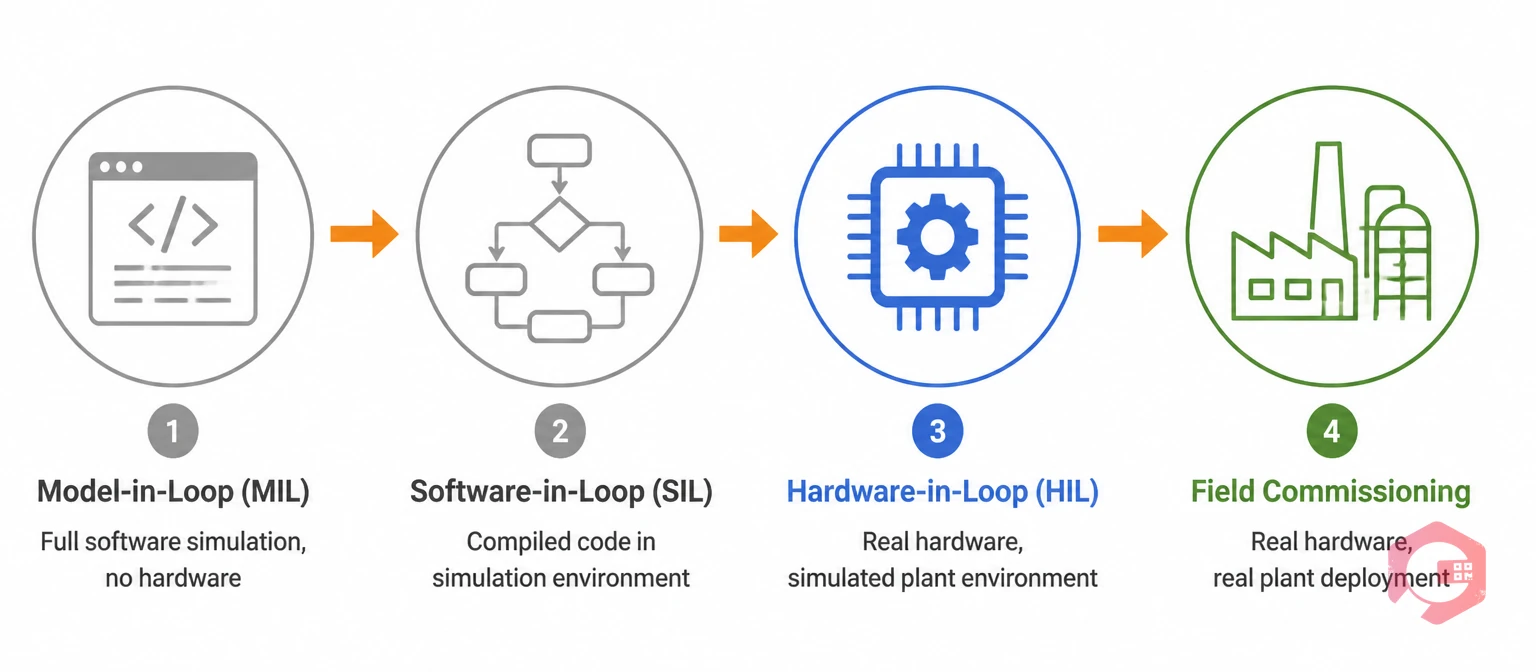
Engineers developing predictive maintenance systems typically work through a layered testing progression. Understanding where HIL fits — and why it cannot be skipped — is critical for maintenance leaders evaluating their PdM validation strategy.
HIL occupies the essential middle ground: high enough fidelity to expose real hardware problems, but controlled enough to inject specific failure modes safely. For proactive maintenance systems where alert accuracy is everything, HIL is not optional — it is the difference between a PdM program that works and one that gets abandoned after three months of nuisance alarms.
A complete predictive maintenance pipeline moves from raw sensor data through feature engineering, model training, threshold setting, alert generation, and finally work order creation. HIL testing has a defined, high-value role at three specific stages of this pipeline.
The biggest practical challenge in building PdM models is the scarcity of labeled failure data. Production assets run reliably most of the time — which is exactly what you want, but it means that genuine bearing failures, motor winding faults, and hydraulic seal degradation events are rare in your historical dataset. A model trained only on "normal" operation cannot reliably distinguish early-stage failure signatures from normal variation.
HIL solves this by allowing engineers to inject controlled, repeatable faults directly into the hardware under test. Want to train a model to detect bearing inner-race defects? Load a bearing inner-race fault signature into the simulation, connect it to the vibration sensor module, and capture labeled data as the hardware responds to the fault progression. According to a NIST report on industrial control system testing, fault injection through HIL reduces the time to build a usable labeled dataset by 70% compared to waiting for organic field failures.
Once a PdM model is trained, it needs alert thresholds: the specific sensor reading values at which the system should generate a maintenance alert. Setting these thresholds wrong is the most common cause of PdM program failure. Too sensitive and you flood technicians with false positives until they ignore every alert. Too conservative and failures slip through.
HIL allows threshold validation at the hardware level. Engineers can run the DUT through hundreds of simulated operating cycles — normal load, partial fault, progressive fault, catastrophic fault — and observe exactly where the model's alert fires relative to the actual fault state. This produces threshold settings calibrated to real hardware behavior, not simulation artifacts or theoretical assumptions from sensor datasheets.
The output of a predictive maintenance alert is only valuable if it correctly triggers a work order in your maintenance management system. HIL test environments can be extended to include the full alert-to-CMMS workflow: the simulation fires a fault, the DUT generates an alert, and the integration layer is verified to create the right work order type with the right priority and asset assignment. This end-to-end testing catches integration failures — wrong asset IDs, missing priority flags, broken API calls — before they cause real maintenance delays in production.
HIL testing originated in aerospace and automotive engineering, but its application in predictive maintenance validation has expanded across asset-intensive industries where the cost of PdM false positives or missed failures is high.
Despite its value, HIL testing introduces specific operational and technical challenges that maintenance engineers and reliability teams need to plan for.
HIL testing produces a validated predictive maintenance system — reliable alert thresholds, proven sensor logic, and a labeled fault dataset that supports accurate models. But the value of that system only reaches the maintenance floor when it integrates cleanly with the platform your technicians and maintenance managers actually use every day.
Cryotos CMMS serves as the operational hub where HIL-validated PdM alerts become structured, trackable maintenance action. Here is how the connection works in practice.
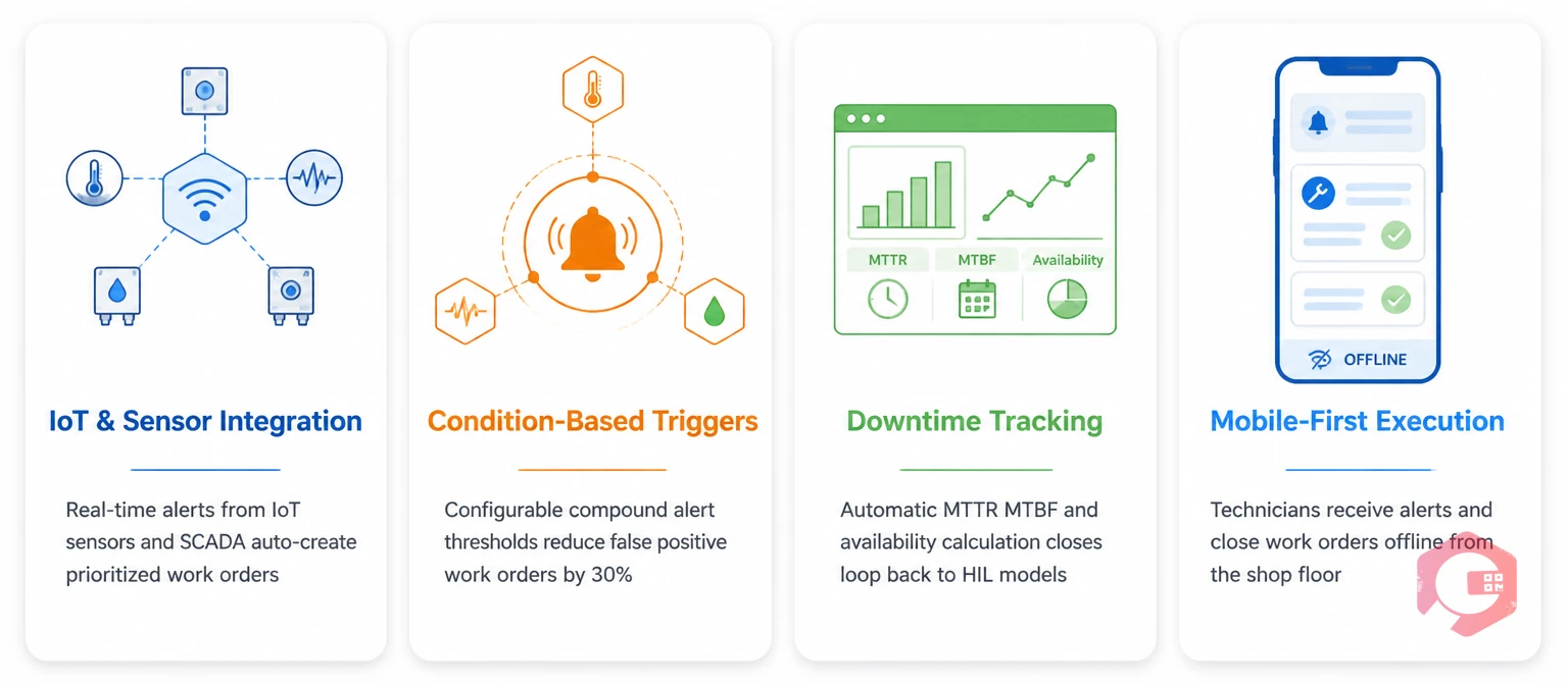
Cryotos integrates directly with IoT sensor platforms, SCADA systems, and PLC data feeds through its IoT meter reading module. When a sensor threshold validated through HIL testing is crossed on a live asset, Cryotos receives that alert in real time and automatically creates a prioritized maintenance work order — no human intermediary required. The work order is pre-populated with the relevant asset history, maintenance checklist, and spare parts requirements, so the technician arrives informed and prepared.
Cryotos supports configurable alert thresholds with compound logic — work orders can be triggered when a single parameter crosses its limit, or only when multiple conditions are met simultaneously (vibration AND temperature elevated, for example). This mirrors the conditional threshold logic validated during HIL testing, reducing false positive work orders that erode technician trust in the PdM program. Teams using Cryotos with IoT-connected assets report a 30% reduction in unplanned downtime and 25% faster repair times.
Every condition-triggered work order in Cryotos feeds the downtime tracking module, automatically calculating MTTR, MTBF, and asset availability. This operational data closes the loop back to the HIL test environment: if field MTBF on a particular asset diverges from HIL-validated predictions, maintenance engineers know the plant model needs re-parameterization before the next threshold refinement cycle.
Cryotos's mobile app gives field technicians complete work order access, digital checklists, and photo capture capability — all in offline mode for areas without connectivity. The same technician who receives a HIL-validated vibration alert at 2 AM can close the work order from the shop floor, capturing the exact failure mode observed, the parts replaced, and the time to repair. This data feeds directly into the BI dashboard and into the maintenance history that future HIL model training draws from.
A digital twin is a continuously updated virtual model of a physical asset, used primarily for monitoring and analysis during operation. HIL testing uses a simulation model as a controlled test environment for validating hardware — the simulation is a test tool, not a live operational replica. Digital twins and HIL simulation can use similar underlying plant models, but their purpose and integration into the maintenance workflow are distinct. HIL is pre-deployment validation; a digital twin is ongoing operational intelligence.
No — HIL testing is most justified for high-criticality assets where a missed failure or excessive false alerts carries significant cost or safety risk. For lower-criticality assets with well-understood failure modes and widely available failure data, the cost of building a full HIL test environment may not be warranted. A practical approach is to use HIL validation for Tier 1 critical assets and to rely on historical data and field calibration for lower-criticality equipment.
For a well-defined PdM system applied to a single asset class, a HIL validation cycle typically runs 4 to 12 weeks, depending on the complexity of the plant model and the number of fault modes being characterized. Organizations with existing simulation infrastructure can compress this significantly. The first HIL program in an organization always takes longer because it includes building the plant model and validation workflow from scratch; subsequent programs on similar asset types reuse much of that work.
Yes — the output of HIL testing (validated thresholds, fault signatures, alert logic) integrates with cloud-based CMMS platforms through standard API connections. The HIL test environment validates what the alert should look like; the CMMS platform handles what happens when it fires. Cryotos supports REST API integration with IoT platforms and SCADA systems, making it straightforward to connect HIL-validated alert outputs to Cryotos maintenance workflows without custom development.
If your team is building or scaling a predictive maintenance program and wants to connect validated IoT alerts directly to structured maintenance workflows, Cryotos CMMS provides the IoT integration, automated work order creation, and real-time downtime analytics that turn PdM system outputs into measurable operational results. Book a free demo today and see how Cryotos handles condition-based maintenance workflows end to end.


Cryotos AI predicts failures, automates work orders, and simplifies maintenance—before problems slow you down.