
Motor Current Signature Analysis (MCSA) is a non-invasive condition monitoring technique that diagnoses mechanical and electrical faults in induction motors by analysing the frequency spectrum of the stator current. Rather than requiring physical access to the motor or installation of vibration sensors on the casing, MCSA works entirely from the existing electrical supply connections — a current clamp on the motor leads is all the hardware required. The current waveform carries a wealth of diagnostic information: fault conditions inside the motor alter the magnetic flux, which in turn modulates the stator current at characteristic frequencies that are mathematically predictable for each fault type.
For industrial maintenance teams, MCSA offers a powerful complement to vibration analysis. It detects faults that vibration cannot reach — internal rotor bar cracks, stator winding asymmetries, and load-side mechanical problems — and it can be performed online, under load, without any interruption to production. According to a study published in the IEEE Transactions on Industrial Electronics, MCSA can detect developing rotor bar faults with greater than 90% accuracy at loads above 50% of rated capacity, making it one of the most reliable motor fault detection methods available for continuous operation environments.
MCSA works on a fundamental principle: a perfectly healthy induction motor draws a symmetrical, sinusoidal current at the supply frequency. Any mechanical or electrical asymmetry inside the motor — a cracked rotor bar, a bearing defect, air gap eccentricity — disturbs the magnetic flux distribution and generates characteristic sidebands in the current spectrum. These sidebands appear at predictable frequencies around the supply frequency fundamental, and their amplitude relative to the fundamental indicates fault severity.
The diagnostic process involves four steps: capture the stator current waveform using a current clamp or transducer, apply a Fast Fourier Transform (FFT) to convert the time-domain signal to a frequency spectrum, identify fault-characteristic sideband frequencies using the known formulae for each fault type, and compare sideband amplitudes against established baselines to assess severity. The result is a quantitative, repeatable assessment of motor health that can be trended over time to track fault progression.
MCSA was originally developed for large, critical motors in power generation and petrochemical environments where the cost and safety risk of vibration sensor installation was prohibitive. The technique has since been extended to motors from 1 kW upward, and portable MCSA analysers have made the technology accessible to maintenance teams without specialist signal processing expertise.

MCSA is particularly effective at detecting faults with strong current signature characteristics. The five fault categories below represent the most diagnostically reliable MCSA applications in industrial practice.
Rotor bar faults are the most widely documented MCSA application. A broken or cracked rotor bar disrupts the magnetic field symmetry and generates sidebands at (1 ± 2s)f₁, where s is the slip and f₁ is the supply frequency. At 50 Hz supply with 3% slip, the fault frequencies appear at 47 Hz and 53 Hz. Amplitude growth in these sidebands over successive measurements indicates progressive rotor bar damage.
Rotor bar faults typically develop from thermal cycling, starting stress, or manufacturing defects, and progress slowly — often over 6 to 18 months — before causing winding damage or catastrophic failure. Early detection through MCSA allows planned rotor replacement during a scheduled outage, avoiding the far more costly consequences of an in-service failure in a production-critical motor.
Bearing faults generate vibration at frequencies related to the bearing geometry and rotational speed. These mechanical vibrations modulate the air gap flux and produce current sidebands at f₁ ± n·fᵇᵉᵃᴼ, where fᵇᵉᵃᴼ represents the bearing defect frequency (BPFO, BPFI, BSF, or FTF depending on which bearing element is affected). MCSA detects these bearing fault signatures through the current spectrum, providing an alternative or complement to traditional vibration envelope analysis.
The diagnostic sensitivity of MCSA for bearing faults is highest in motors with rotor-mounted components that are directly connected to the motor shaft, where bearing vibration couples efficiently into the electrical circuit. In motors with flexible couplings or soft mounts, vibration-based monitoring may provide better sensitivity for bearing fault detection.
Air gap eccentricity occurs when the rotor centre does not coincide with the stator centre, producing a non-uniform air gap. Static eccentricity (fixed offset) and dynamic eccentricity (rotating offset) each produce characteristic current harmonics at f₁ ± k(R/p)(1-s)f₁, where R is the number of rotor slots, p is the pole pair number, and k is an integer. Eccentricity develops from manufacturing tolerances, bearing wear, shaft bow, or thermal distortion, and if left unaddressed can cause rub contact between rotor and stator with catastrophic consequences.
Turn-to-turn insulation faults in the stator winding alter the phase current balance and produce characteristic harmonic content in the current spectrum. These faults are among the most difficult to detect by vibration analysis alone, making MCSA particularly valuable for stator condition assessment. MCSA-based stator fault detection is most reliable during offline testing (surge testing or motor circuit analysis), but online monitoring through current harmonic trending can identify developing asymmetries between scheduled outage windows.
Faults in coupled equipment — pump impeller cavitation, gearbox tooth wear, fan blade imbalance — can be detected through the motor current signature because the load torque variation they generate modulates the motor current at frequencies related to the mechanical fault and the shaft speed. This makes MCSA a useful diagnostic tool for the complete motor-load system, not just the motor itself, and allows a single current measurement point to provide diagnostic information about both the motor and its driven equipment.
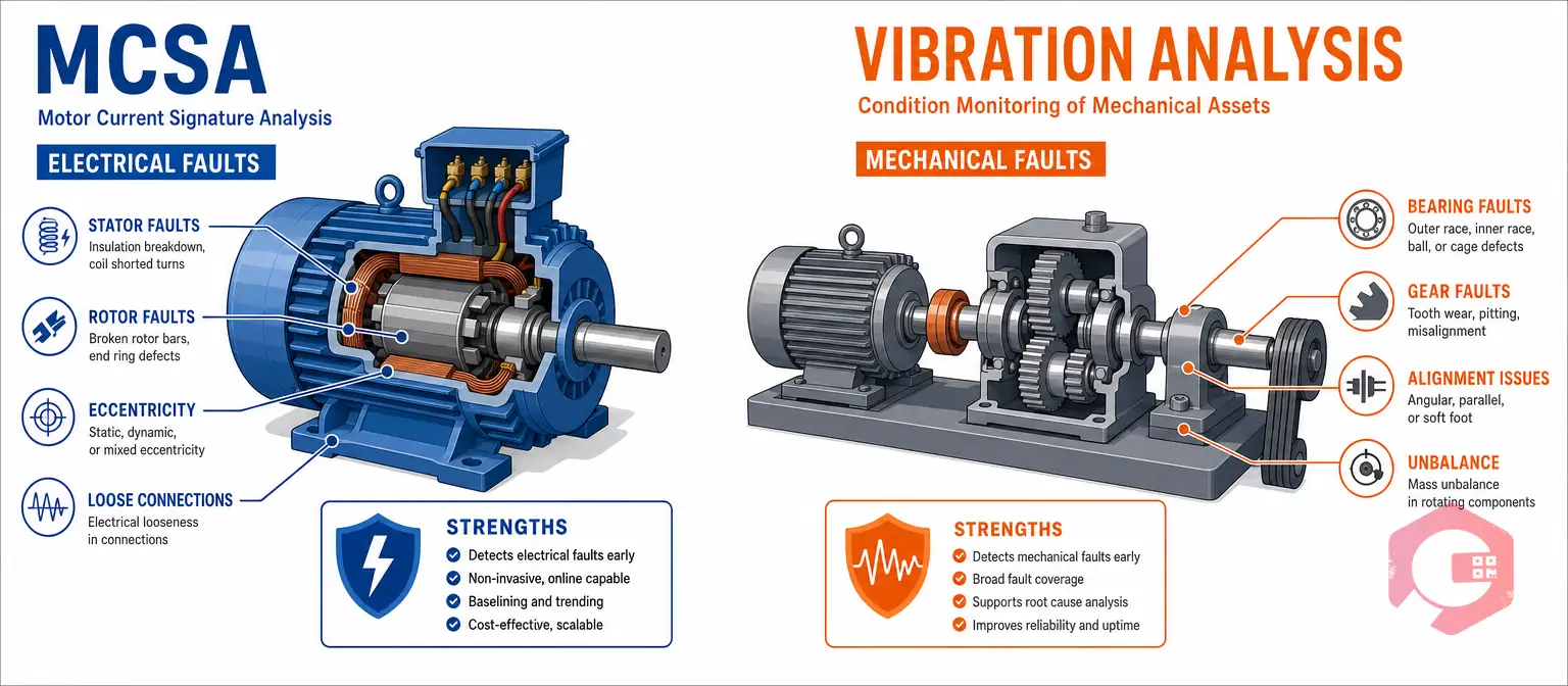
MCSA and vibration analysis are complementary techniques, not competing alternatives. Each has diagnostic strengths and limitations that make them most effective when used together as part of a comprehensive motor condition monitoring programme.
MCSA is uniquely effective for detecting faults that originate electrically or that do not couple efficiently into the motor casing as vibration. Rotor bar faults, stator winding asymmetries, and air gap eccentricity produce strong, characteristic current signatures that vibration analysis may miss entirely. MCSA requires no sensor installation on the motor body, making it practical for motors in difficult access locations, hazardous area classifications, or enclosures that cannot be opened safely under load. The technique is inherently non-intrusive, requires no contact with rotating parts, and can be performed online at full load — capturing the fault signatures that only appear under operational conditions.
Vibration analysis provides richer diagnostic information for mechanical drivetrain faults beyond the motor: gearboxes, couplings, rolling element bearings under light load, and structural resonances. The frequency resolution achievable through high-frequency vibration enveloping typically provides earlier and more specific bearing fault detection than MCSA alone, particularly for low-speed or lightly-loaded applications. Vibration analysis is also better suited to motors that are not operating at full load, where MCSA sensitivity for rotor bar and eccentricity faults reduces significantly.
The most robust motor condition monitoring programme uses both techniques in combination. MCSA provides electrical and internal fault detection that vibration analysis cannot reach; vibration analysis provides high-resolution mechanical drivetrain diagnostics that complement the current-based picture. For critical motors — those rated above 75 kW or on the critical path of production — deploying both techniques is justified by the cost of a single unplanned failure. For less critical motors, MCSA alone provides cost-effective coverage because it requires no sensor installation and minimal measurement time per unit.
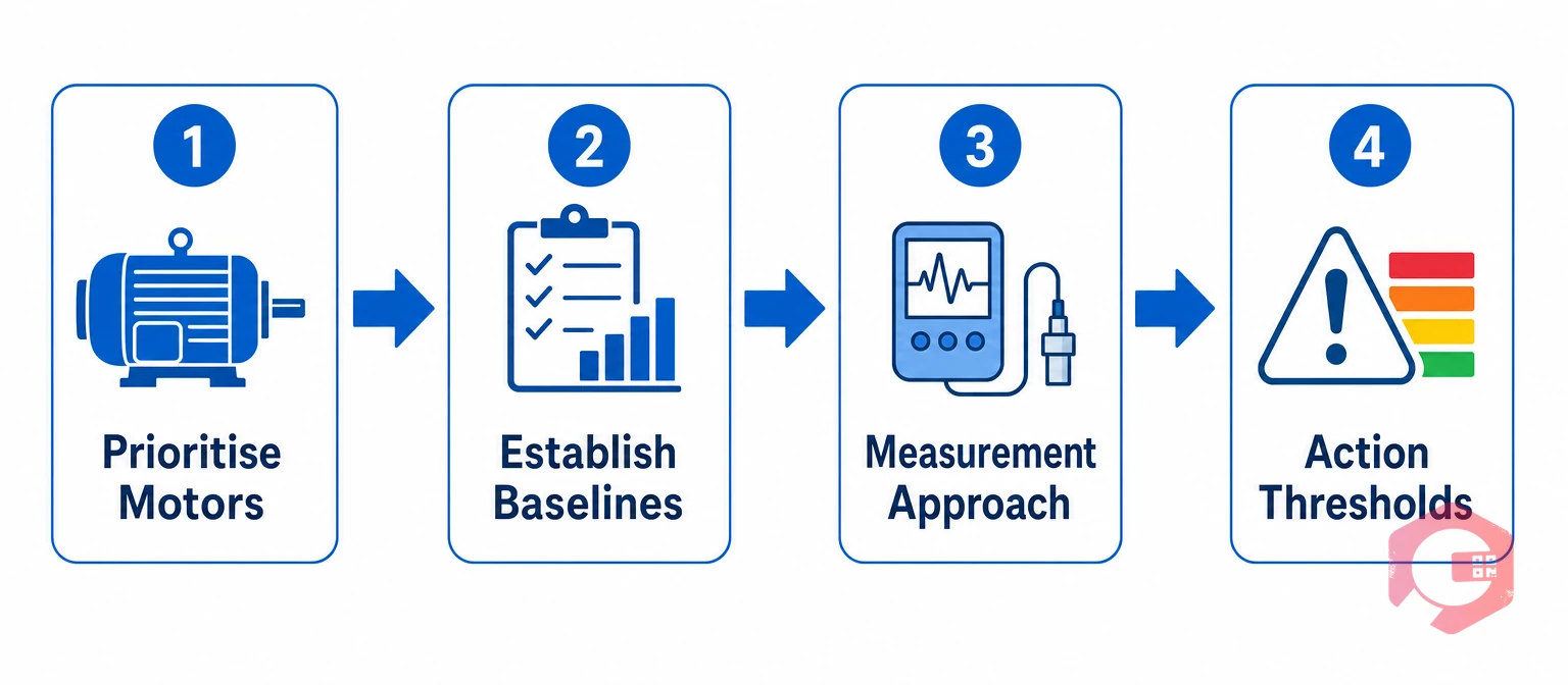
Start with a criticality classification of your motor fleet. Focus initial MCSA deployment on motors above 37 kW, motors with no available spare, motors on the critical production path, and motors in environments where physical inspection is difficult or hazardous. This approach concentrates diagnostic effort where failure consequences are highest and delivers the fastest return on the time invested in baseline measurement.
MCSA is a trending technique: its diagnostic value comes from comparing current measurements over time, not from a single absolute reading. For each priority motor, capture a baseline current spectrum under representative load conditions (ideally above 60% of rated load) within the first 30 days of programme launch. Document the motor nameplate data, supply frequency, measured slip, and load level for each baseline — this context is essential for correctly calculating fault frequencies and interpreting subsequent measurements.
Two MCSA measurement approaches suit different operational contexts. Route-based periodic measurement uses a portable MCSA analyser carried by a technician on a defined inspection route, taking measurements at each priority motor on a weekly, monthly, or quarterly schedule. Online continuous monitoring uses permanently installed current transducers connected to a condition monitoring system that records and analyses the motor current spectrum continuously. Route-based measurement is cost-effective for facilities with 20 to 200 priority motors; online continuous monitoring is justified for single large critical motors where any delay in fault detection carries major operational risk.
MCSA results need clear interpretation criteria so that measurements translate directly into maintenance decisions. A common three-tier framework classifies fault sideband amplitudes as: Alert (sideband 35–45 dB below fundamental — monitor at increased frequency), Alarm (sideband 25–35 dB below fundamental — plan corrective maintenance within 30–90 days), and Critical (sideband above 25 dB below fundamental — schedule repair at earliest opportunity, consider online derating). These thresholds are typical starting points; refine them based on your specific motor types, operating conditions, and historical fault data over the first 12 to 18 months of programme operation.
The diagnostic value of MCSA is only realised when its findings connect reliably to maintenance action. Without a structured workflow from measurement to work order to resolution, MCSA findings accumulate in a condition monitoring database that nobody acts on, and the programme loses credibility with maintenance management.
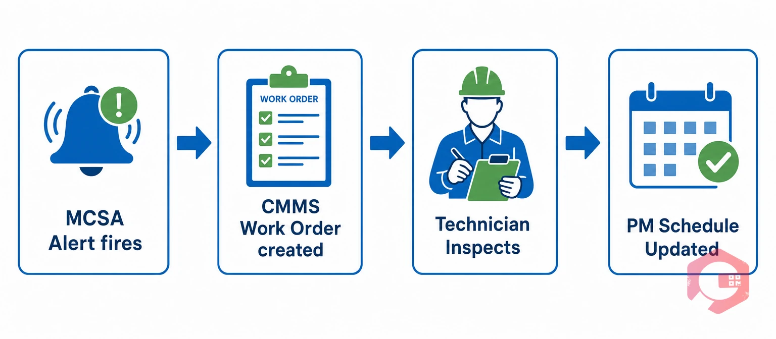
A well-designed MCSA-to-CMMS workflow follows four stages. First, the MCSA measurement produces a fault finding (fault type, severity tier, motor identity). Second, the finding is logged against the motor’s asset record in the CMMS with the relevant data attached — spectrum image, sideband amplitude, load at time of measurement. Third, if the finding meets the Alert or Alarm threshold, the CMMS automatically generates a work order at the appropriate priority level, assigned to the motor maintenance team with the MCSA data and interpretation attached. Fourth, when the corrective work order is completed, the technician logs the findings — what was found physically, what was done, what was replaced — and the motor’s MCSA baseline is updated to reflect the post-repair condition.
Cryotos CMMS supports this workflow through its IoT meter reading and asset management modules. Condition monitoring findings — from MCSA, vibration analysis, oil analysis, or thermography — are logged against the relevant asset record as meter readings with defined alert thresholds. When a reading crosses a threshold, Cryotos automatically creates a high-priority work order linked to the asset, with the measurement data, asset history, and spare parts inventory visible to the assigned technician in the mobile app. The complete chain from sensor reading to completed repair is documented in one system, creating the maintenance history that supports both future diagnostic decisions and regulatory compliance audits.
For facilities with online MCSA monitoring systems, Cryotos integrates directly with SCADA and condition monitoring platforms through its IoT data feed capability, enabling automatic work order creation when MCSA threshold exceedances are detected — without any manual data transfer between systems.
MCSA is practically applicable to induction motors from approximately 7.5 kW upward, provided they are operating above 40 to 50% of rated load during measurement. Below this load threshold, slip is too small for reliable rotor bar fault detection, and other fault signatures become ambiguous. The technique is most widely used on motors from 37 kW to several megawatts in process industry, power generation, and heavy manufacturing environments.
Yes — online measurement under load is both the standard application and one of MCSA’s primary advantages. Measurements are taken using a current clamp on the motor supply cables without interrupting operation. The motor should be running at a stable, representative load during measurement; transient load conditions during startup or speed ramping are not suitable for steady-state MCSA analysis.
The appropriate measurement interval depends on motor criticality and the severity of any developing faults already identified. Healthy critical motors are typically measured monthly or quarterly. Motors showing Alert-level findings are measured weekly to track fault progression rate. Motors at Alarm level are scheduled for corrective work within 30 to 90 days and measured fortnightly in the interim. Once a corrective action is complete, the measurement frequency returns to the baseline interval after a new healthy baseline is established.
No. MCSA and vibration analysis are complementary techniques. MCSA detects electrical and internal motor faults that vibration analysis misses, while vibration analysis provides richer diagnostics for mechanical drivetrain faults and bearing defects under light load. A comprehensive motor condition monitoring programme uses both, targeting each technique at the fault modes it detects most effectively. For facilities with resource constraints, MCSA alone provides valuable coverage for rotor bar and eccentricity faults at low instrumentation cost.
MCSA findings are logged as condition monitoring meter readings against the relevant motor asset record in the CMMS. When a finding meets a defined alert or alarm threshold, the CMMS generates a corrective work order automatically and assigns it to the maintenance team with the relevant measurement data attached. This connection between diagnostic finding and maintenance action is what transforms MCSA from a data collection exercise into a reliability improvement programme. Cryotos CMMS supports this integration through its IoT meter reading and threshold-triggered work order capabilities.


Cryotos AI predicts failures, automates work orders, and simplifies maintenance—before problems slow you down.