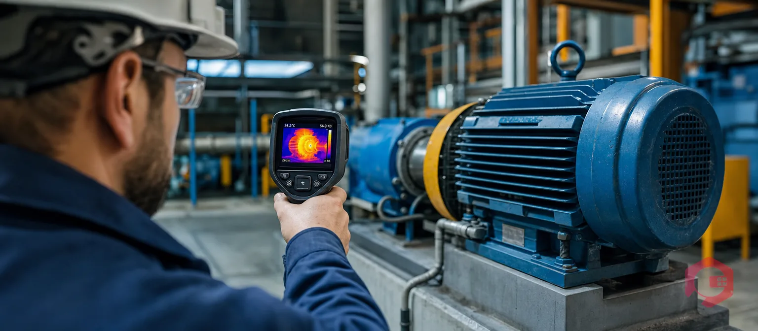
Thermal imaging for motor condition monitoring uses infrared cameras to detect abnormal heat patterns in electric motors and gearboxes before they cause failure. Every electrical and mechanical fault — from a failing bearing to unbalanced windings — produces a distinctive heat signature long before it becomes a breakdown. According to the U.S. Department of Energy, electric motor failures account for roughly 70% of industrial electrical energy consumption, and bearing faults alone cause over 40% of all motor failures. Catching those faults thermally can cut repair costs by 30 to 50% compared to reactive maintenance.
An electric motor running normally produces heat — but it produces it evenly and within predictable limits. When something starts to go wrong, heat concentrates at the failure point. A thermal camera turns that invisible signal into a visible color map you can act on.
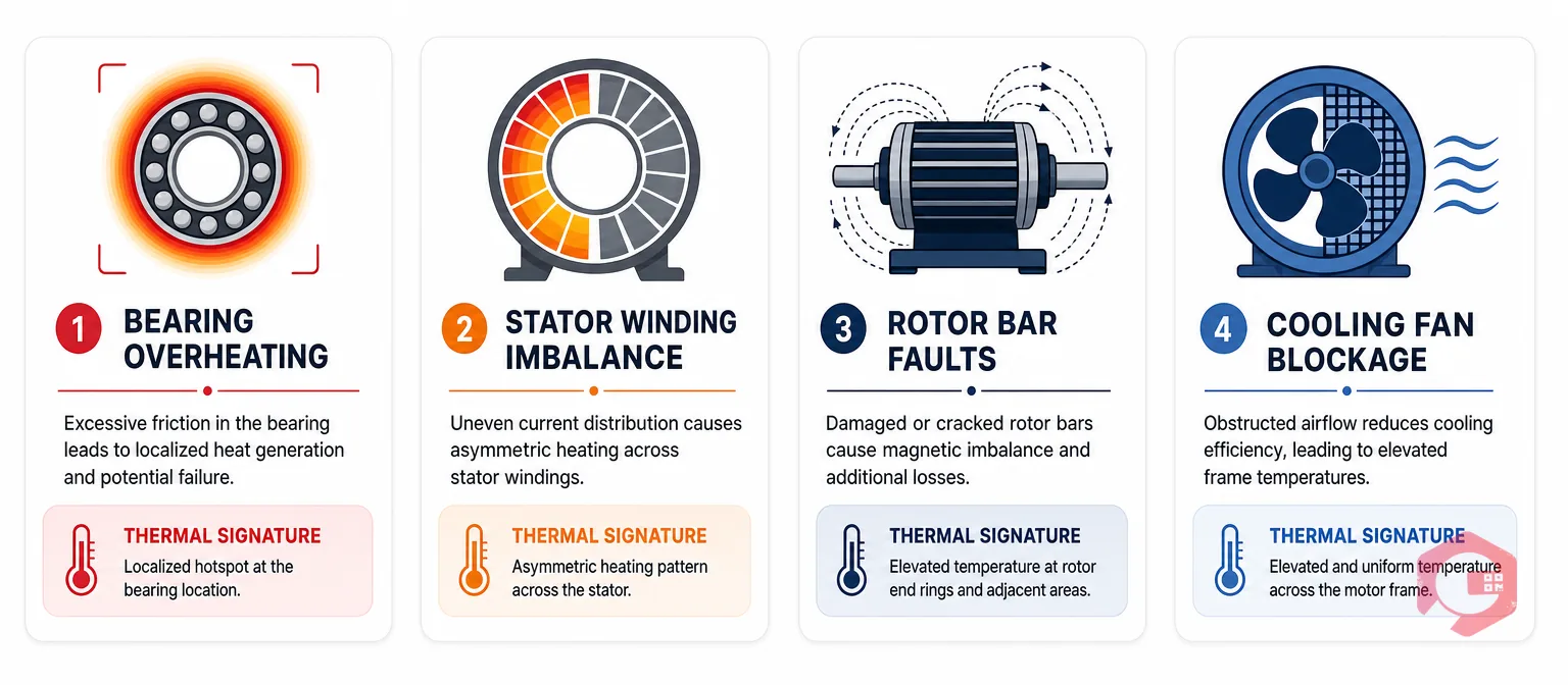
Abnormal signatures to watch for include: hot spots hotter than the surrounding surface by more than 10°C on a bearing housing, asymmetric heating across three-phase connection points pointing to phase imbalance, uniform but excessive surface temperature above motor insulation class limit, and cool spots on a motor that should be warm indicating blocked ventilation.
A single thermal scan of a motor-gearbox drive train can cover multiple potential failure points simultaneously: drive-end and non-drive-end bearing housings, motor terminal box and cable connections, stator frame and end shields, coupling and flexible drive components, and gearbox housing and output shaft seals.
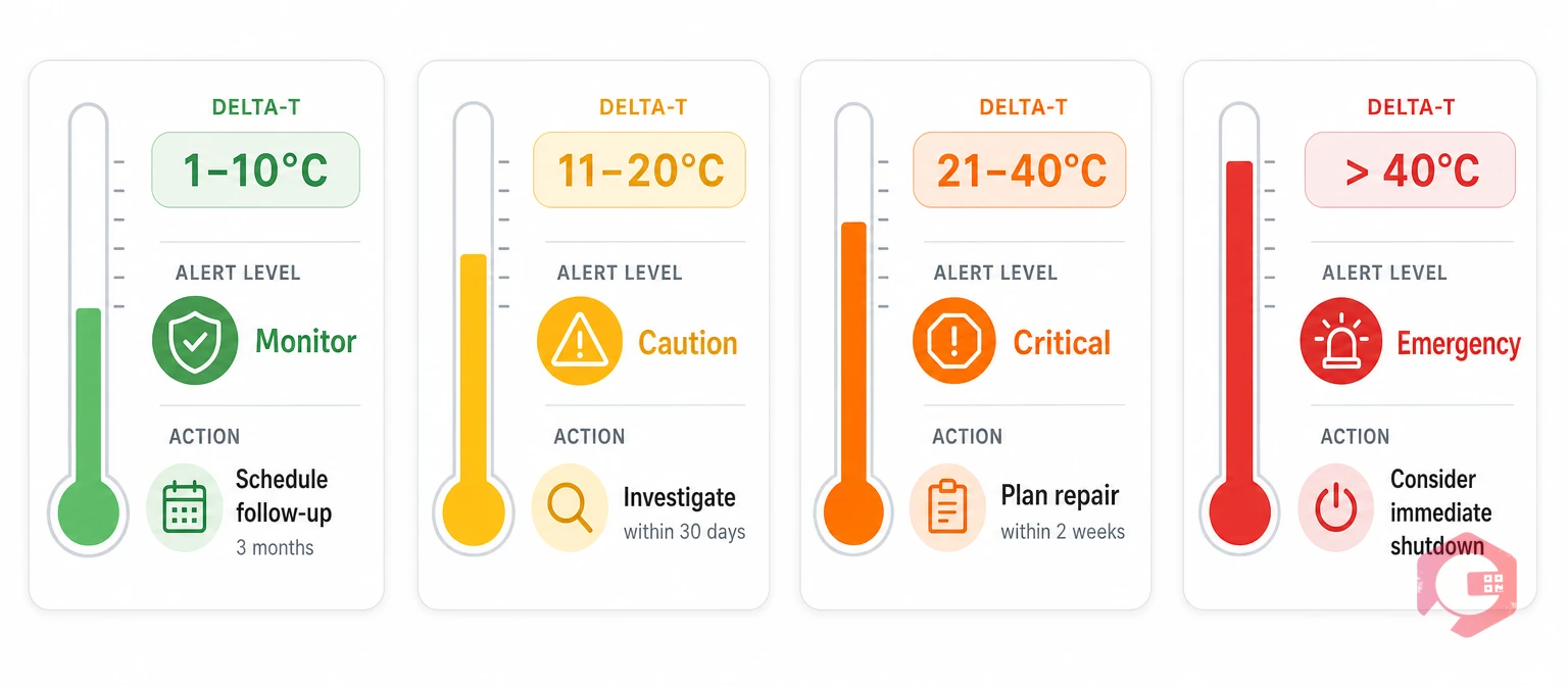
Standard delta-T alert levels used in industrial practice: ΔT 1–10°C above baseline — Monitor, schedule follow-up within 3 months. ΔT 11–20°C — Caution, investigate within 30 days. ΔT 21–40°C — Critical, plan repair within 1–2 weeks. ΔT greater than 40°C — Emergency, consider immediate shutdown. The IEC 60034 standard defines motor insulation classes: Class B (120°C maximum absolute), Class F (145°C — most standard industrial motors), and Class H (165°C).
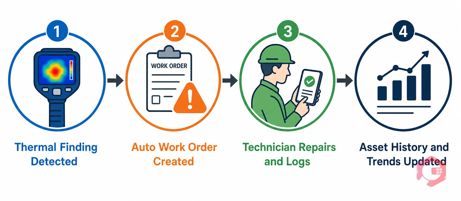
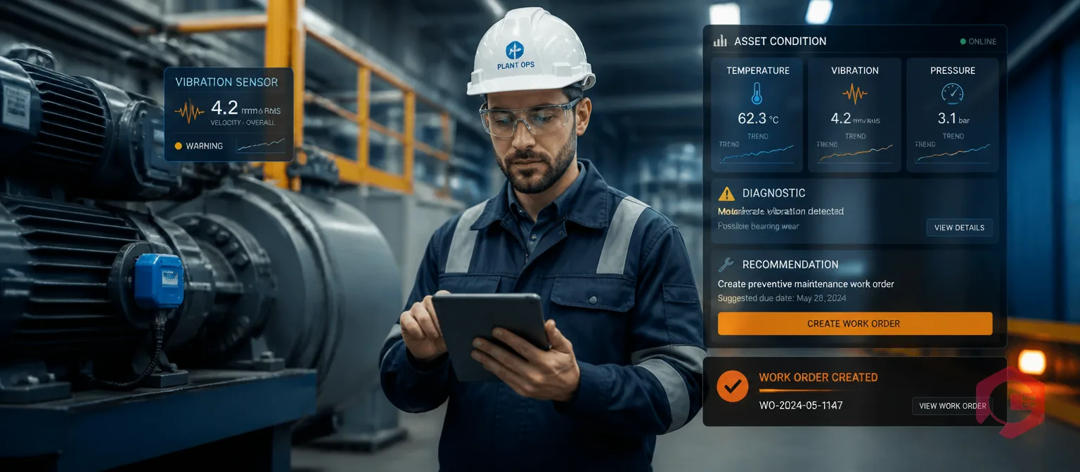
Thermal inspection data only generates value when it drives maintenance action. A connected thermal inspection workflow in Cryotos CMMS works as follows: thermal finding triggers an automatic corrective work order with the asset ID, fault description, thermal image attached, and due date based on ΔT severity. For critical motors, continuous IoT temperature monitoring via IoT meter reading integration can trigger an alert when bearing housing temperature exceeds a set threshold. The BI Dashboard tracks which motors are consistently appearing on thermal inspection findings — identifying chronic problem assets that need engineering review rather than repeated repairs.
For critical production motors, quarterly inspection is a good baseline. For important but non-critical motors, semi-annual inspection is typical. NFPA 70B recommends annual thermal inspection as a minimum. After any motor repair or rewind, inspect within the first week of operation.
A fully loaded motor housing typically runs 20–40°C above ambient under normal conditions. Per IEC 60034, Class F insulation allows a winding temperature rise of up to 105°C above a 40°C ambient — but housing surface readings will be significantly lower than internal winding temperatures.
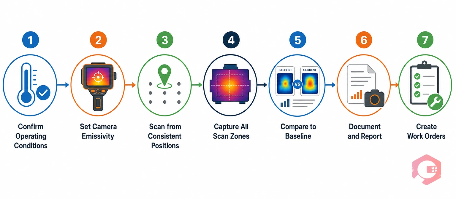
For painted motor housings, use an emissivity setting of 0.90 to 0.95. Bare or polished metal surfaces have much lower emissivity and will give falsely low temperature readings. Apply high-emissivity tape to the measurement spot and allow it to reach thermal equilibrium before scanning.
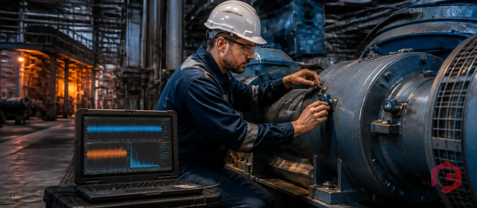
Thermal imaging and vibration analysis are complementary tools. Thermal imaging tends to detect electrical faults and early-stage lubrication problems earlier. Vibration analysis is more sensitive to mechanical faults like rotor bar cracks and advanced bearing wear. Best practice is to use both.
Thermal imaging gives your maintenance team a fast, non-invasive way to catch motor and gearbox problems weeks or months before they become failures. Cryotos CMMS helps close that loop: log thermal findings in the field, auto-generate corrective work orders, track asset health trends over time, and integrate IoT sensor alerts directly into your maintenance workflow. Explore Cryotos and see how maintenance teams are turning inspection data into uptime.


Cryotos AI predicts failures, automates work orders, and simplifies maintenance—before problems slow you down.