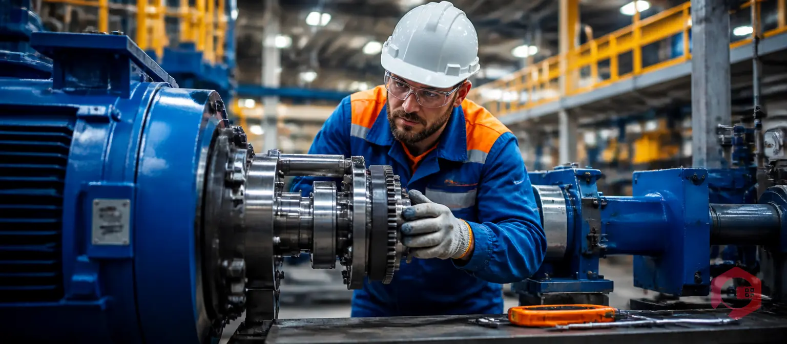
Gear coupling reliability depends on four disciplines working together: precision shaft alignment, correct lubrication, structured inspections, and continuous condition monitoring. Research from the Society for Maintenance and Reliability Professionals (SMRP) consistently shows that coupling failures rank among the top causes of unplanned rotating equipment downtime in manufacturing and heavy industry — yet the overwhelming majority of those failures are preventable. This guide gives your maintenance team a complete, practical roadmap for keeping gear couplings running at peak reliability throughout their full service life.
Key Takeaways
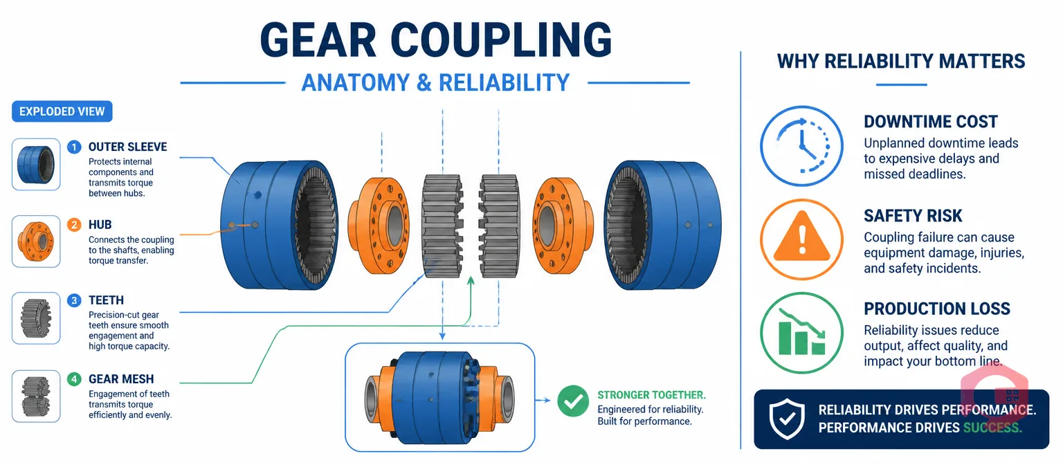
A gear coupling is a mechanical device that transmits torque between two shafts while tolerating small amounts of angular, parallel, and axial misalignment. It consists of two hubs with external gear teeth that mesh with matching internal gear teeth inside a flanged sleeve. That meshing tooth geometry is the key: it allows the coupling to flex under real-world misalignment while continuing to transmit full rated torque — which is why gear couplings are the go-to choice for demanding, high-torque, high-speed applications such as rolling mills, paper machines, centrifugal pumps, marine propulsion drives, and heavy compressors.
Reliability in a gear coupling context means the component consistently performs its power transmission function over its expected service life without unscheduled failure. When reliability breaks down, the damage is rarely contained to the coupling alone. Rising vibration transfers stress to adjacent bearings, seals, and shafts. Misalignment-induced loads accelerate wear throughout the drivetrain. An uncontrolled failure during operation can seize machinery, damage connected equipment, and put operators at risk. The cost of a coupling failure almost always exceeds the cost of preventing it by an order of magnitude.
This is why asset maintenance management for rotating equipment treats gear couplings as critical components deserving their own PM plan — not an afterthought serviced only when something goes wrong.

Understanding how and why gear couplings fail is the fastest path to preventing failure. Most failures trace back to a small set of root causes, each with clear physical symptoms and actionable corrective measures.
Applying reliability-centered maintenance principles to gear coupling programs means systematically identifying these failure modes, assigning each a prevention strategy, and scheduling the PM tasks that address the root cause before failure occurs.
Use the MTBF calculator to establish your gear coupling mean time between failures baseline — then track improvement as your PM program matures.
Misalignment is the single most common root cause of premature gear coupling failure. Getting alignment right at installation and maintaining it throughout the coupling's service life is the highest-return maintenance activity you can perform on rotating equipment.
Every gear coupling deals with three types of misalignment simultaneously. Angular misalignment occurs when the shaft centerlines intersect at an angle rather than running parallel. Parallel (offset) misalignment occurs when shaft centerlines are parallel but laterally offset from one another. Axial misalignment — sometimes called end float — occurs when shafts move toward or away from one another along their common axis during operation. Real installations almost always involve a combination of all three.
The most reliable alignment method for gear couplings is laser alignment using a shaft-to-shaft laser measurement system. Laser alignment delivers accuracy to ±0.001 inches or better — far exceeding what dial indicators can achieve on larger shafts, and eliminating the bracket sag errors that make dial indicator readings unreliable on long spans. For critical or high-speed couplings, laser alignment is the minimum acceptable method.
Always align to the coupling manufacturer's published tolerances, not generic targets. Many coupling failures attributed to the alignment being close are actually cases where misalignment was within a technician's rough approximation but outside the manufacturer's actual specification. Tolerance data is typically expressed in TIR (Total Indicator Runout) at specified span.
Check and document alignment at four points in the coupling lifecycle: during initial installation, after any connected equipment is serviced or repositioned, after thermal expansion events (alignment must be performed at operating temperature for equipment with significant thermal growth), and at every scheduled PM interval. Many plants discover that foundations settle and pipe strain shifts alignment over time — making periodic re-check mandatory rather than optional.
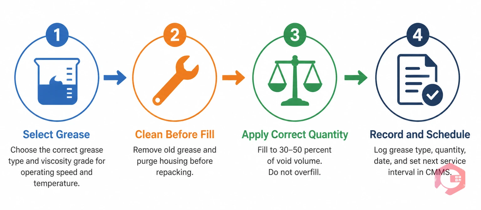
Lubrication failures cause or contribute to the majority of gear coupling problems across industry. The gear teeth inside a coupling operate under high contact stress with micro-motion between mating surfaces at every revolution — conditions that demand a lubricant specifically engineered for the application, not whatever grease happens to be available on the shelf.
Gear couplings designed for grease lubrication require a coupling-specific grease — typically an NLGI Grade 1 or 2 formulation with high tackiness, extreme pressure (EP) additives, and resistance to centrifuging. Standard bearing greases are too light in consistency and centrifuge out of the coupling at speed, leaving gear teeth running dry within hours. AGMA 9001 provides the industry reference standard for coupling lubricant selection based on operating speed, temperature, and coupling type.
For high-speed couplings operating above 3,600 rpm, or for couplings subject to high ambient temperatures, consult the manufacturer's specification before selecting a lubricant. Some high-speed couplings are designed for oil lubrication with a continuous circulation system rather than grease — confusing the two lubrication systems is a common and costly installation error.
Most coupling manufacturers recommend relubrication every 3,000 to 5,000 operating hours or annually — whichever comes first. Operating conditions that shorten intervals include high ambient temperature, high operating speed, heavy loading, frequent reversals, or evidence of accelerated lubricant degradation during inspection. When in doubt, shorten the interval rather than extending it.
Correct relubrication procedure matters as much as interval. Always fully purge the old lubricant from the coupling before refilling with fresh material — mixing degraded grease containing wear particles, moisture, and oxidation products with fresh grease reduces the fresh lubricant's performance immediately. Inject fresh grease until purge ports show clean material, then seal and document the service.
For critical gear couplings, lubricant sampling at each relubrication event provides leading indicator data on coupling health. A laboratory analysis reporting elevated iron or chromium content, increased moisture levels, or abnormal viscosity signals that something inside the coupling is degrading — before any external symptom becomes visible. This practice extends lubricant intervals on couplings in good condition while flagging deteriorating units for earlier inspection.
A structured inspection routine is your primary defense against coupling failures developing undetected between PM intervals. Use the asset and equipment inspection checklist as a foundation and customize it for gear coupling-specific checks.
Scheduled inspections are essential, but condition-based maintenance takes gear coupling reliability to the next level by detecting problems developing between scheduled intervals — giving your team time to plan a repair before an unplanned failure forces one.
Vibration analysis is the most widely used condition monitoring technique for rotating equipment including gear couplings. A misaligned or worn gear coupling produces a characteristic vibration signature that increases at 1x and 2x running speed frequencies. Comparing current vibration spectra against established baseline readings for each coupling detects developing problems early. The Reliable Plant gear coupling guide notes that 1x and 2x vibration signatures are diagnostic markers for misalignment and tooth wear respectively. Many reliability programs define alert thresholds and alarm thresholds that trigger progressive response actions from increased monitoring frequency to planned shutdown.
Coupling temperature rises as tooth-to-tooth friction increases due to misalignment, lubricant starvation, or wear. Regular thermography scans of operating couplings — using a calibrated infrared camera — detect hot spots that are not visible or measurable by other means. This is particularly valuable for couplings inside guards or covers where visual inspection is impractical while running. Trending temperature readings over time is more valuable than any single measurement.
For critical couplings, taking a lubricant sample at each service interval and submitting it for laboratory analysis provides a window into what is happening inside the coupling between inspections. Key wear metals (iron, chromium, nickel), particle count, moisture content, and viscosity all provide diagnostic signals that guide maintenance decisions. A lab report showing rapidly increasing iron content from a coupling that looks fine on visual inspection is a call to stop and open it — invariably, the inspection finds tooth damage that visual examination would have missed for another cycle.
The difference between a gear coupling maintenance program that works and one that drifts is systematic execution. Individual technicians doing their best work are not enough — alignment checks get skipped during production pressure, relubrication intervals slip when the shift is short-staffed, and inspection findings do not get recorded in a way that builds trend data. A CMMS enterprise asset management solution solves those execution gaps by making the program systematic and measurable.
Cryotos CMMS gives maintenance teams practical tools for gear coupling reliability at every level of the program.
Plants using Cryotos to manage rotating equipment maintenance programs report a 30% reduction in unplanned downtime and 25% faster repair turnaround times — results driven by the combination of systematic PM execution, faster work order response, and data-driven maintenance decisions.
Shaft misalignment is the most common root cause of gear coupling failure. When angular, parallel, or axial misalignment exceeds the coupling's rated tolerance, gear tooth contact concentrates at tooth edges rather than across the full tooth face, causing accelerated wear, elevated temperature, and ultimately tooth fracture or fatigue failure. Lubrication failure is the second most common cause, often occurring together with misalignment.
Most gear coupling manufacturers recommend relubrication every 3,000 to 5,000 operating hours or annually — whichever comes first. This interval shortens in high-speed, high-temperature, or heavily loaded applications. Always follow the manufacturer's published recommendation for the specific coupling model and operating conditions, and always fully purge old lubricant before refilling with fresh material.
Gear couplings require a coupling-specific grease — typically NLGI Grade 1 or 2 with extreme pressure (EP) additives and high resistance to centrifuging. Standard bearing greases are too light in consistency and will centrifuge out of the coupling at operating speed, leaving gear teeth running dry. Consult AGMA 9001 and the coupling manufacturer's specification for lubricant selection guidance.
Early warning signs of a failing gear coupling include elevated vibration at 1x and 2x running speed, higher-than-baseline operating temperature detected by infrared thermometer, audible clicking or grinding noises, visible grease leakage from coupling seals, and lubricant samples showing elevated wear metal content. Any of these signals warrants prompt inspection before the coupling progresses to complete failure.
A CMMS improves gear coupling reliability by ensuring PM work orders for lubrication, inspection, and alignment are scheduled and executed consistently — not dependent on individual memory or manual planning. Digital inspection checklists capture quantitative readings that enable trend analysis. Complete asset history supports root cause analysis when failures occur. Together, these capabilities convert a reactive maintenance approach into a proactive, data-driven program.
Gear coupling failures are preventable with the right maintenance program in place. Schedule a free demo to see how Cryotos helps maintenance teams build and execute systematic gear coupling reliability programs that cut unplanned downtime.




Cryotos AI predicts failures, automates work orders, and simplifies maintenance—before problems slow you down.