
A failure-finding interval (FFI) is the maximum allowable time between inspections of a protective device to ensure its hidden failure probability stays within an acceptable risk threshold. For protective devices like pressure relief valves, fire suppression systems, safety interlocks, and emergency shutdown valves, FFI is not optional — it is the calculation that keeps dormant failures from becoming catastrophic events. According to the U.S. Occupational Safety and Health Administration (OSHA), the majority of catastrophic process failures involve a safety system that had been in a failed state for an unknown period before the incident. Setting the right inspection frequency — and enforcing it — is the difference between a protective layer that works and one that only looks like it does on paper.
This guide covers the failure-finding interval formula, device-specific inspection frequencies, common calculation mistakes, and how a modern CMMS automates FFI scheduling to keep your protective layers functional and auditable.
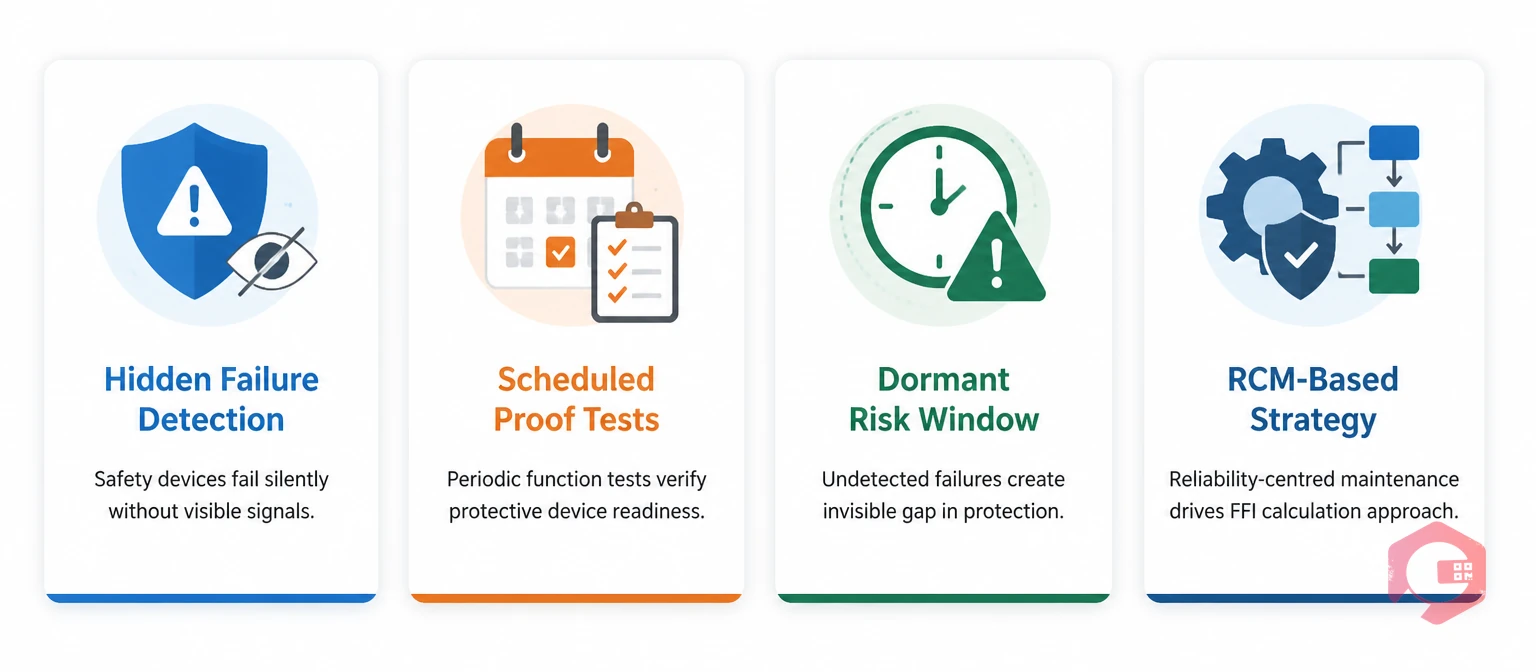
A failure-finding interval is a scheduled inspection task designed specifically to detect whether a protective device has failed in a dormant (hidden) state. Unlike run-to-failure or time-based preventive maintenance tasks, an FFI task does not fix anything — it tests whether the device can still do its job when called upon. If the device fails the test, a corrective action is triggered. If it passes, the next FFI is scheduled for the calculated interval ahead.
The concept comes directly from reliability-centered maintenance (RCM), where failure modes are classified by whether they are evident or hidden to the operator under normal operating conditions. Protective devices — by design — only activate during an abnormal event. A pressure relief valve does not pop open during normal operation. A fire suppression system does not discharge on a normal working day. An emergency shutdown valve sits closed until a process upset demands it to open. This means a failure of any of these devices will remain completely invisible until the moment protection is actually needed.
A failure is hidden when no operating crew member will notice it during normal operations. A pressure transmitter that feeds a high-pressure alarm can fail in a way that leaves the alarm permanently silenced — and no one knows until an overpressure event occurs with no warning. A fire damper that has seized open due to corrosion is invisible on the operations dashboard but catastrophically wrong when fire breaks out. These are precisely the failure modes that FFI tasks are designed to surface before they matter.
Most maintenance strategies focus on assets that fail in ways operators can detect — vibration rises, temperature increases, throughput drops. Protective devices are fundamentally different. They are designed to sit idle and activate only under the conditions they are protecting against. This idle-by-design nature means:
The practical implication is that protective devices need their own maintenance strategy: one built on function testing at calculated intervals, with results tracked and correlated to failure rates over time. Preventive maintenance software that supports dynamic interval scheduling — driven by actual failure data — is the operational backbone of an effective FFI program.
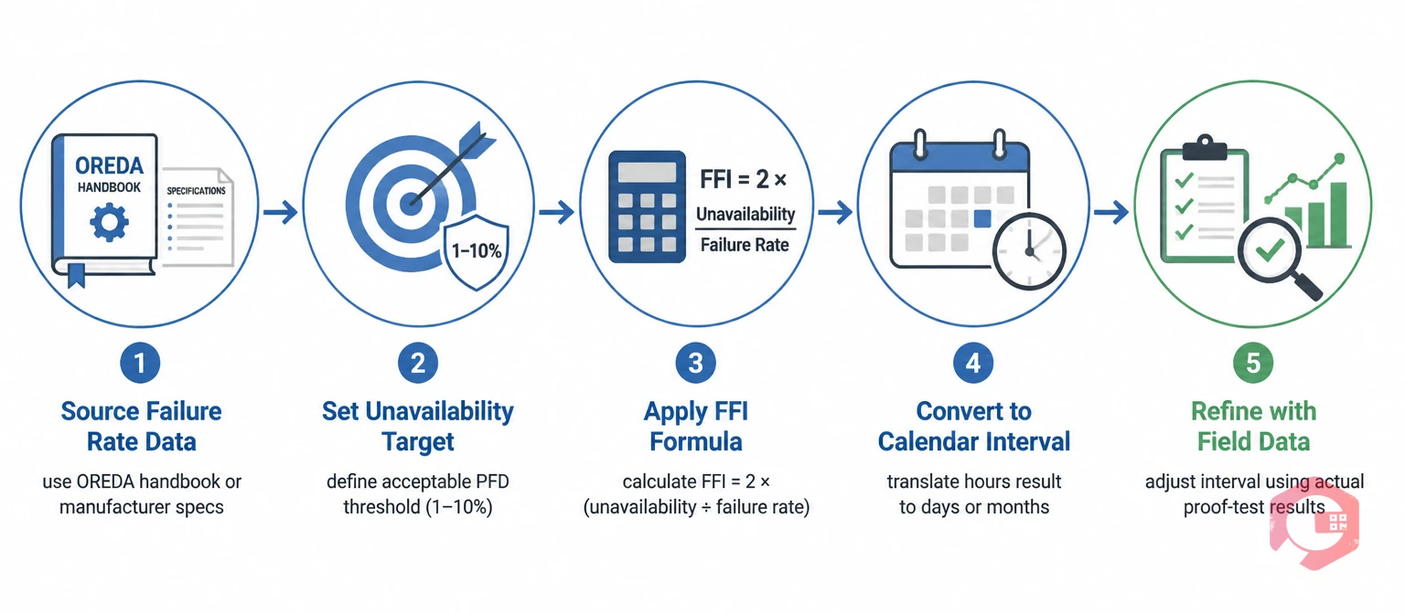
The standard RCM-derived formula for a failure-finding interval is based on balancing three variables: the unavailability target (the acceptable probability that the device is in a failed state at any given moment), the probability that a demand event will occur, and the mean time to restore or detect the failure. The simplified working formula used in most industrial FFI programs is:
FFI = 2 × (Target Unavailability ÷ Failure Rate)
Where:
For example, if a safety interlock has a dormant failure rate of 0.0001 failures per hour (one failure per ~10,000 hours) and your target unavailability is 5%, the calculation is: FFI = 2 × (0.05 ÷ 0.0001) = 1,000 hours, or approximately 42 days. You would inspect this device at least once every 42 days to maintain the 5% unavailability target.
For most maintenance teams, the exact dormant failure rate is not initially available from their own records. In this case, start with conservative published rates from reliability databases such as OREDA, then refine the interval based on actual proof-test results over time. If 20 consecutive proof tests show zero failures, your real failure rate is lower than assumed and you can justify extending the interval. If failures are found at a rate higher than assumed, shorten the interval immediately and investigate the cause with a root cause analysis. Use the failure rate calculator to help compute the right starting values for your specific devices.
While the FFI formula gives you a site-specific calculated interval, the following reference table provides widely used starting-point inspection frequencies drawn from IEC 61511, API 689, NFPA standards, and industry practice. These are not substitutes for a site-specific FFI calculation — they are starting benchmarks to validate your calculations against.
| Protective Device | Typical FFI Range | Key Proof-Test Action | Governing Standard |
|---|---|---|---|
| Pressure Relief Valve (PRV) | 12–24 months | Lift test at set pressure; inspect seat and disc | API 510 / API 576 |
| Safety Instrumented System (SIS) Interlock | 3–12 months (SIL-dependent) | Full functional test including trip initiation | IEC 61511 |
| Emergency Shutdown Valve (ESDV) | 3–6 months | Partial stroke test; full stroke test at shutdown | API 6D / IEC 61511 |
| Fire Detection and Alarm System | 1–6 months | Detector activation test; panel annunciation check | NFPA 72 |
| Fire Suppression System (Sprinkler/Gaseous) | 6–12 months | Flow test; control valve inspection; agent weight check | NFPA 25 / NFPA 2001 |
| Gas Detection System | 1–3 months | Bump test with calibration gas; alarm setpoint verification | ISA-TR84.00.04 |
| Safety Relief Valve (Rupture Disk) | 24–36 months or process-dependent | Visual inspection; pressure holding test | ASME Section VIII |
| Electrical Overcurrent Protection (Circuit Breaker) | 12–36 months | Trip test at rated current; contact resistance check | NFPA 70B / IEEE C37.06 |
When your calculated FFI is significantly shorter than the typical range shown above, that is a signal to re-examine your failure rate assumption or evaluate whether the device specification is appropriate for the application. When your calculated FFI is significantly longer than the typical range, treat the typical range as an upper limit until you have accumulated enough proof-test history to justify the extension.
Even teams that calculate FFIs correctly often erode their protective value through flawed execution. These are the most common failure modes in failure-finding programs:
These mistakes are preventable with the right process and the right tools. A workflow automation layer that ties proof-test results to automatic interval recalculation and corrective work order generation closes the loop that manual processes leave open.
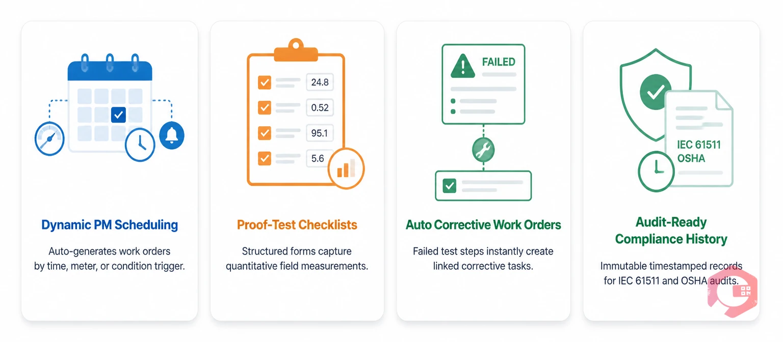
Managing failure-finding intervals manually — through spreadsheets, paper logs, or calendar reminders — creates the same hidden failure problem you are trying to solve. A missed proof test due to a scheduling error is a period of uncontrolled unavailability. A result that never gets analyzed is a data point that never improves your FFI calculation. A corrective action that is not formally raised and tracked may or may not be completed before the next demand event.
A modern CMMS solves each of these gaps through four specific capabilities:
Teams using Cryotos CMMS have reported a 30% reduction in unplanned downtime and 25% faster repair times after connecting their protective device inspection programs to structured PM workflows. For safety-critical assets where the failure mode is hidden, that reduction represents not just maintenance efficiency but real risk reduction across the operation. See how Cryotos maintenance management software supports protective device FFI programs from scheduling through compliance reporting.
A preventive maintenance interval targets failure modes that degrade over time and affect normal equipment operation — lubrication intervals, filter replacements, and calibration cycles. A failure-finding interval targets hidden failure modes in protective devices that only activate during abnormal events. The goal of a PM interval is to prevent failure. The goal of an FFI is to detect a failure that has already occurred but cannot be observed during normal operations.
Start with published reliability databases. The OREDA (Offshore and Onshore Reliability Data) handbook is the most widely used source for process industry safety devices. The EXIDA database covers safety instrumented systems specifically. Use a conservative (higher) failure rate initially, which will produce a shorter inspection interval. As you accumulate proof-test results, recalculate using your actual observed failure rate. Within three to five years of data collection, your site-specific rate will be more reliable than any handbook estimate.
Only if they operate in identical conditions and service environments. A pressure relief valve protecting a clean water system has a different dormant failure rate than an identical valve protecting a sour gas service with potential for seat corrosion and disc fouling. Device type is a starting point; service conditions, process fluid, environmental exposure, and maintenance history all affect the actual failure rate and therefore the correct FFI.
Three actions are required immediately: isolate or compensate for the loss of protection (put in place a compensating safety measure if the process must continue), raise a corrective work order to restore the device to functional status, and record the failure details for FFI recalculation. The time the device was in the failed state should be estimated and documented for your unavailability records. The FFI should be reviewed immediately after the corrective work order is closed — if the device failed before the scheduled FFI expired, the interval needs to be shortened.
IEC 61511 (Functional Safety of Safety Instrumented Systems) requires that proof-test intervals for safety instrumented functions (SIFs) be calculated to maintain the required Safety Integrity Level (SIL). For a SIL 1 function, the overall probability of failure on demand (PFDavg) must be between 0.01 and 0.1. The proof-test interval is one of the primary variables in the PFDavg calculation. An FFI that is too long will push PFDavg above the SIL 1 limit, meaning the safety layer is no longer meeting its design intent — even if it passes every proof test it receives.
Setting the right failure-finding intervals for your protective devices requires calculation, field data, and a system that enforces the schedule without exception. If your current program relies on spreadsheets or manual calendars, you have a hidden availability risk in the maintenance process itself — separate from the device failure rates you are trying to manage. Cryotos CMMS gives maintenance and reliability teams the scheduling engine, structured proof-test checklists, automatic corrective action workflows, and compliance-ready audit trails to run a failure-finding program that actually maintains the protective value your safety layers were designed to deliver. Book a free demo today to see how Cryotos handles protective device FFI scheduling across your entire asset register.


Cryotos AI predicts failures, automates work orders, and simplifies maintenance—before problems slow you down.