
Vibration sensors for condition monitoring are devices that measure mechanical oscillations in equipment to detect early signs of wear, imbalance, misalignment, or bearing failure before a breakdown occurs. Choosing the right sensor type is one of the most critical decisions in any predictive maintenance program — the wrong sensor produces misleading data, and misleading data leads to missed failures or unnecessary repairs that cost just as much.
According to a Plant Engineering report on equipment downtime, unplanned failures cost industrial manufacturers an estimated $50 billion per year. Most of those failures — particularly in rotating equipment — show clear vibration signatures days or weeks before they become critical. Getting the sensor selection right is the first step to catching them in time.
This guide covers the six main types of vibration sensors used in condition monitoring, how each one works, where each performs best, and how to connect sensor data to your maintenance workflows so alerts turn into resolved work orders.
Key Takeaways
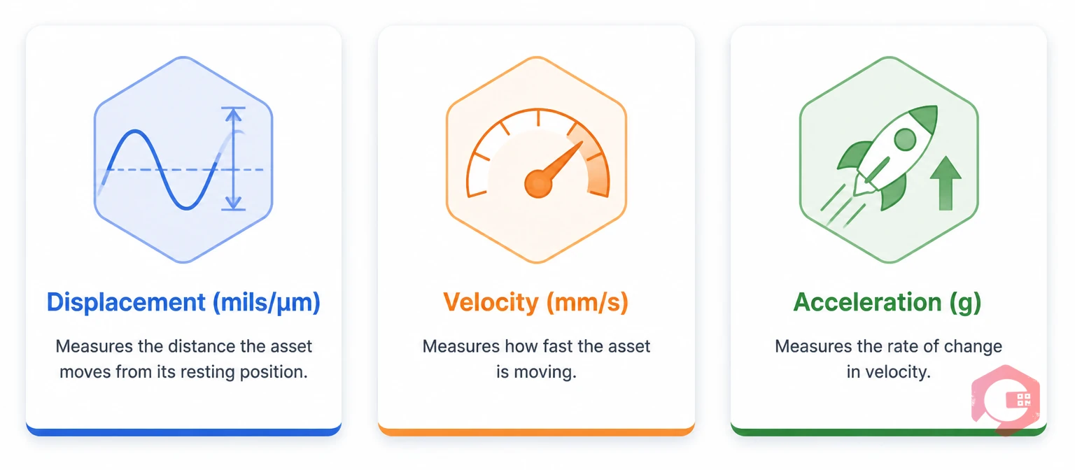
A vibration sensor converts mechanical motion — displacement, velocity, or acceleration — into an electrical signal that a monitoring system can measure and interpret. In condition-based maintenance, these signals are continuously compared against a baseline to detect deviations that indicate a developing fault.
The relationship between sensor type and the measurement it produces is critical. Different failure modes produce different vibration signatures at different frequency ranges. A bearing defect typically appears at high frequencies above 1 kHz. A shaft imbalance appears at low frequencies near the running speed. An oil film resonance in a sleeve bearing appears at sub-synchronous frequencies. No single sensor covers every failure mode equally well — which is exactly why understanding the sensor types matters.
In a connected condition monitoring system, vibration sensors feed data to a CMMS or monitoring platform. When readings cross a pre-defined threshold, the system automatically generates a maintenance work order, assigns it to the right technician, and pulls the asset history — all before the fault causes a production stoppage. Cryotos CMMS supports this IoT integration directly through its IoT meter reading module, turning raw sensor signals into structured, actionable maintenance tasks.
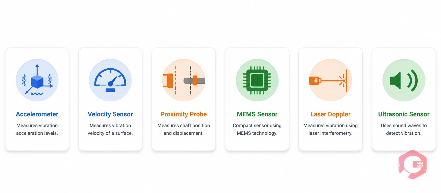
Accelerometers measure the acceleration of vibration in units of g (gravitational acceleration) or m/s². They are the most common sensor type in industrial condition monitoring because they cover an exceptionally wide frequency range — typically from 0.5 Hz to 20 kHz or higher — which means a single accelerometer can detect both low-frequency imbalance and high-frequency bearing defects on the same asset.
Most industrial accelerometers use a piezoelectric crystal element that generates a charge proportional to the acceleration applied to it. When the machine vibrates, the crystal deforms slightly, producing a voltage signal that the monitoring system converts to acceleration data. The signal is then processed through Fast Fourier Transform (FFT) analysis to break it into its frequency components — revealing the specific fault frequencies associated with imbalance, misalignment, bearing wear, or gear mesh problems.
Accelerometers are the right choice for most rotating equipment: motors, pumps, fans, compressors, gearboxes, and machine tool spindles. They perform particularly well for bearing fault detection because bearing defect frequencies fall in the mid-to-high frequency range where accelerometers are most sensitive. For continuous monitoring on critical assets, accelerometers are typically permanently mounted at bearing housings using threaded studs — the most accurate and repeatable mounting method.
Track accelerometer threshold alerts automatically with Cryotos's preventive maintenance software to turn sensor data into scheduled work orders without manual intervention.
Velocity sensors measure vibration velocity — how fast a surface is moving — in units of mm/s (peak) or in/s. They were the dominant sensor type in industrial vibration monitoring before accelerometers became cost-effective, and they remain highly useful for a specific class of assets and fault modes.
Traditional velocity sensors contain a coil of wire suspended in a magnetic field. When the housing vibrates, the coil moves relative to the magnet and generates a voltage proportional to velocity. These sensors are self-generating — they require no external power supply. Modern velocity sensors increasingly use an accelerometer internally and integrate the signal electronically to produce a velocity output.
Velocity sensors are most effective in the 10–1,000 Hz frequency range, making them well-suited for detecting the most mechanically significant vibration problems: imbalance, misalignment, looseness, and resonance. The ISO 10816 standard for evaluating machine vibration severity specifies velocity (mm/s RMS) as the primary measurement quantity — which means velocity sensors produce data that directly maps to internationally recognized severity levels without additional conversion.
Proximity probes — also called eddy current probes or displacement transducers — measure the distance between the probe tip and the shaft surface directly. They do not measure vibration through the bearing housing; they measure the actual shaft motion inside the bearing. This makes them the industry standard for large rotating machines where shaft orbit and radial clearance are critical parameters.
A proximity probe contains a coil that generates a high-frequency magnetic field. When a conductive metal shaft enters that field, eddy currents form in the shaft surface, reducing the coil's inductance. The change in inductance is measured as a voltage change directly proportional to the gap between the probe tip and the shaft. Two probes mounted 90° apart in the same radial plane produce shaft orbit data — the actual path the shaft center traces inside the bearing clearance.
Steam turbines, gas turbines, large centrifugal compressors, and large pumps with fluid-film (sleeve) bearings are the primary applications. The API 670 machinery protection standard mandates proximity probes for radial vibration monitoring on turbomachinery. For these machines, proximity probes detect shaft instability, oil whirl, oil whip, and rubbing conditions that surface-mounted accelerometers miss entirely.
Use the MTBF calculator to establish your turbomachinery reliability baseline before deploying proximity probes and to measure the improvement after condition monitoring is live.
MEMS (Micro-Electro-Mechanical Systems) sensors are miniaturized accelerometers fabricated using semiconductor manufacturing processes. They integrate mechanical sensing elements and electronic signal processing on a single silicon chip. MEMS sensors have driven the explosion in low-cost, wireless IIoT vibration monitoring over the past decade and are central to any large-scale condition monitoring deployment.
A MEMS accelerometer contains a tiny proof mass suspended by microscale spring elements etched into silicon. When the chip accelerates due to vibration, the proof mass deflects, changing the capacitance between the mass and fixed electrodes. This capacitance change is converted to a voltage by on-chip electronics, producing a complete sensor and signal conditioning circuit in a package smaller than a fingernail.
MEMS sensors are the practical choice for wide-scale IIoT deployment on low-to-medium criticality assets where continuous monitoring adds significant value but the cost of piezoelectric sensors with wired cabling would be prohibitive. A single facility might deploy dozens or hundreds of MEMS-based wireless sensors on motors, pumps, fans, and conveyor drives — continuously streaming vibration data to a condition monitoring platform that feeds work order triggers directly into the asset maintenance management software.
Laser Doppler Vibrometers (LDV) measure vibration without physical contact by directing a laser beam at a surface and measuring the Doppler frequency shift of the reflected beam. The frequency shift is directly proportional to the surface velocity at that point. LDVs produce velocity or displacement data with exceptional accuracy across a very wide frequency range — from sub-Hz to several MHz in specialized systems.
LDVs are the preferred tool when contact-based sensors are not practical: high-temperature surfaces such as furnace walls and kiln shells, thin or fragile structures where a sensor would add mass and distort the measurement, rotating components where a slip ring or wireless transmitter would complicate the setup, and surfaces that are electrically live or chemically aggressive. They are also used extensively in R&D and for validating finite element models against physical measurements.
Ultrasonic sensors detect high-frequency sound emissions — typically 20 kHz to 100 kHz — generated by mechanical friction, turbulence, and electrical discharge. In condition monitoring, they catch incipient bearing defects at the very earliest stage, before the defect produces vibration amplitudes large enough for conventional accelerometers to detect reliably. This makes them a powerful complement to accelerometer-based vibration analysis.
Contact ultrasonic sensors use a piezoelectric element that couples to the machine surface through a metal waveguide, detecting ultrasonic stress waves that propagate through the material. The detected high-frequency signals are heterodyned down to the audible range for real-time listening and simultaneously recorded for quantitative analysis. Airborne ultrasonic sensors use a microphone element sensitive to frequencies above human hearing.
Ultrasonic monitoring is most valuable as a complementary technique on critical rotating assets. For slow-speed machinery below 300 RPM — vertical turbines, paper machine rolls, rotary kilns — where conventional vibration analysis struggles because fault frequencies fall at very low amplitudes, ultrasonic sensors often provide clearer early warning. They are also the primary tool for bearing lubrication optimization: the distinctive sound of insufficient lubrication is detectable ultrasonically well before thermal or vibration signatures appear.
Selecting the right sensor comes down to matching sensor characteristics to the asset's criticality, failure modes, and operating environment. Use the comparison below to narrow your choice:
Additional selection criteria to consider:
A sensor mounted incorrectly hides real faults and creates phantom ones. Four rules cover most industrial scenarios:
Spend the extra time on proper mounting. The sensor is only as good as its mechanical connection to the asset. Monitor your downtime tracking data before and after deploying sensors to quantify the reduction in unplanned failures — it's the most straightforward way to prove ROI to leadership.
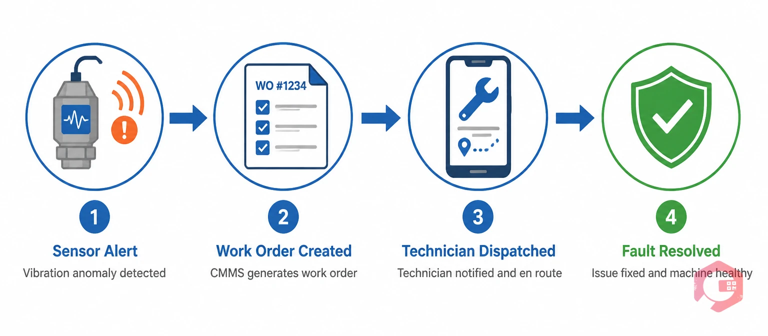
Vibration sensors only deliver value when the data they produce reaches the people who can act on it and triggers the right maintenance response at the right time. This is the gap many condition monitoring programs fail to close: sensors are installed and data is collected, but alert-to-action takes days because the monitoring system is disconnected from the maintenance execution system.
Integrating your vibration monitoring platform with a maintenance management system like Cryotos CMMS closes this gap completely. When a sensor threshold is crossed, Cryotos automatically creates a prioritized work order with the asset's full maintenance history, relevant spare parts from inventory, and the assigned technician — all triggered in real time. The technician receives the work order on the Cryotos mobile app, completes the inspection, logs findings, and closes the job with a digital sign-off. The entire event from sensor alert to work order closure becomes a permanent, searchable record in the asset history.
For facilities using the BI Dashboard as part of their reliability program, Cryotos calculates MTBF and MTTR automatically from work order data, giving maintenance managers the KPIs they need to demonstrate the program's value to operations leadership. Teams using Cryotos for condition-based maintenance workflows report a 30% reduction in unplanned downtime and 25% faster repair times — the direct result of cutting the time between fault detection and corrective action.
Schedule a free demo to see how Cryotos connects your vibration sensors to a full maintenance execution workflow — from IoT threshold alert to closed work order.
Piezoelectric accelerometers are the most widely used vibration sensors in industrial condition monitoring. They cover the broadest frequency range of any contact sensor (0.5 Hz to 20 kHz+), making them suitable for detecting both low-frequency mechanical faults like imbalance and high-frequency bearing defects in a single measurement. They are available in a wide range of form factors, environmental ratings, and price points to suit most industrial applications.
Accelerometers measure vibration acceleration in g or m/s² and cover a wide frequency range, making them better for detecting high-frequency faults like bearing defects. Velocity sensors measure vibration velocity in mm/s and are optimized for the 10–1,000 Hz range where mechanically significant faults like imbalance and misalignment appear. The ISO 10816 standard for machinery vibration severity is expressed in velocity units, so velocity measurements map directly to internationally recognized severity limits without conversion.
Proximity probes should be used on machines with fluid-film (sleeve) bearings — large turbines, large compressors, and large pumps — where direct shaft measurement is required. Accelerometers measure bearing housing motion; proximity probes measure actual shaft motion inside the bearing clearance. The API 670 machinery protection standard mandates proximity probes for turbomachinery radial vibration monitoring. For rolling element bearing machines, accelerometers are the appropriate choice.
MEMS sensors are appropriate for wide-scale IIoT deployment on low-to-medium criticality assets where cost and wireless connectivity are priorities. For high-criticality assets — particularly where high-frequency bearing defect detection above 5 kHz is required, or where measurement accuracy in high-temperature environments is essential — piezoelectric accelerometers remain the more capable choice. Most mature condition monitoring programs use both: MEMS for broad coverage and piezoelectric for the highest-criticality assets.
The most effective approach is to integrate your vibration monitoring platform with a CMMS that supports IoT data ingestion. When sensor readings exceed defined thresholds, the CMMS automatically creates a maintenance work order, assigns it to the correct technician, and attaches the relevant asset history and recommended actions. Cryotos CMMS supports this integration through its IoT meter reading module, connecting to SCADA systems, PLCs, and IIoT platforms to turn sensor alerts into structured work orders without manual intervention.



Cryotos AI predicts failures, automates work orders, and simplifies maintenance—before problems slow you down.